
CNC Cutting Parameters Chart vs Real Machining Data Which To Trust
Troubleshooting CNC Surface Finish: How to Tweak Your Parameters When the Chart Fails
Surface finish problems in CNC machining can bother even the best workers. When the CNC cutting parameters chart fails to bring the wanted results, you have to go past usual numbers and adjust your work based on everyday shop conditions. This piece checks out ways to spot and change main machining settings to make surface quality better when the chart by itself cannot lead the way.
Why Does the CNC Cutting Parameters Chart Sometimes Fail?
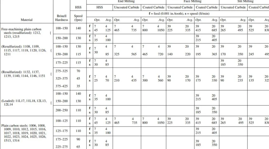
The CNC cutting parameters chart acts as a basic guide. It lists suggested numbers for speed, feed, and depth of cut in many kinds of materials. Yet these charts picture perfect setups. They count on exact tool shapes, firm holds, and steady material strength. In the actual shop, little shifts in machine tuning, tool damage, or part clamping can lead to big changes in the finish.
You may spot shake marks or uneven feel even after sticking to the chart. This usually happens because of a difference between book numbers and real cutting moves. A shiny aluminum piece could have small cuts at speeds that look best on paper. That’s the start of fixing. You figure out what your machine and material show you.
Take a simple case from a small shop I heard about. They followed the chart to the letter for some aluminum blocks. But the finish came out rough. It turned out the machine stand was loose, adding extra wobble. A quick tighten fixed it all.
Identifying Common Surface Finish Problems
Surface finish troubles mostly split into three groups. These include tool problems, setting mismatches, and outside effects. Before you tweak feeds or speeds without looking, it pays to pin down which group your problem fits.
Tool Wear and Geometry
A blunt or nicked cutting side will nearly always make the surface rougher. This holds true no matter the feed rate or spindle speed. Even tiny nicks at the tool point can put clear lines on close-tolerance parts like mold pieces or plane arms. You must change or sharpen tools before they hit bad wear points.
Picture this. In one factory run, we had tools that looked okay but had micro-nicks. They ruined a set of inserts for a big mold job. Checking with a magnifier saved the next batch.
Machine Vibration
Shakes quietly wreck surface quality. They can start from old bearings, weak clamps, or even a match between spindle speed and the setup’s own shake rate. If you see repeating designs on the part face, shakes are most likely the cause.
Shops often miss this until patterns show up. Once, a team traced lines back to a fan nearby. Turning it off cleared the issue in seconds.
Material Properties
Not every group of metal acts the same. Changes in strength or inner stress spread can change chip breaking and heat making. When cutting stainless steel or titanium mixes, even small shifts in makeup can change how the material handles push.
For example, a batch of stainless came in with uneven hardness. Our standard cuts led to poor chips and hot spots. We tested samples first after that, which helped avoid repeats.
How Should You Adjust Feed Rate and Spindle Speed?
After you see that settings play a role in the trouble, turn your attention to feed rate and spindle speed. These two affect surface finish the most.
Adjusting Feed Rate
Feed rate sets how much material each tooth takes per turn. A high feed rate boosts cutting push and leaves deeper tool lines. A low one might rub instead of cut. The way to do it is to find a middle point where chips break off neat without too much strain.
Let’s say you mill aluminum with a 10 mm end mill at 12,000 RPM. You notice dull lines along the cut. Try raising the feed a bit, by 10 to 15 percent. This pushes for clean slicing over dragging.
In a real test on flat panels, this small bump smoothed the streaks. The parts passed inspection without extra work.
Adjusting Spindle Speed
Spindle speed changes both heat and chip clearing. Higher speeds often help finish on soft metals. But they can overheat hard ones. If your chart picks 8,000 RPM for mild steel and you see blue color near the sides, lower speed in 10 percent steps. Keep going until the color turns back to usual gray.
You should also try dodging shake matches. Small shifts in RPM, say plus or minus 200, can move shake waves to steady the cut.
One operator shared how tweaking RPM by 150 fixed a buzzing sound on steel rods. It was a game-changer for their daily output.
What Role Does Depth of Cut Play?
Depth of cut shapes how load spreads and heat builds in machining. A deep cut takes more material. But it raises bend forces on tools and clamps. On the flip side, several light cuts give better hold. Yet they can stretch the total time without need.
When going after a nicer surface finish after rough cuts, think about leaving extra stock of 0.1 to 0.2 mm. Use it for finish passes at lower depth, around 0.05 to 0.1 mm. This makes a gentler touch between tool sides and the work face.
In turning work above all, wrong depth often causes built-up edge. That’s a small lump of material stuck to the tool point. It pulls along the surface and makes bumpy cuts.
Consider a turning job on shafts. We started with 0.5 mm depth and got drag marks. Dropping to 0.1 mm passes cleaned it up. Time increased by 25 percent, but the finish shone.
How Can Coolant Type Affect Surface Finish?
Coolant pick often slips by in fix talks for finish woes. But it hits straight on oiling at the tool-chip spot and heat steadiness in cuts.
Water-mixed coolants do great at pulling heat in fast aluminum milling. But they may not oil well for stainless steel finish cuts. In those spots, changing to half-made fluids with more oil can cut rub lines sharply.
For no-liquid setups, usual in plane-level titanium, air blow cooling with small amount lubrication helps keep chips out. It also cuts down rust spots on done faces.
A team once switched from water to oil-mix on tough steel. The friction marks vanished, and tool life stretched by half. Simple change, big payoff.
Should You Modify Toolpath Strategy?
Now and then, surface issues come not from settings but from how you use them on hard shapes. Toolpath planning takes a big part here.
For instance, climb milling tends to give smoother ends than regular milling. It cuts rub at enter spots. In the same way, steady cutter bite plans stop quick load jumps that mark pass shifts.
On bent faces like fan blades or forms, step height control in CAM software sets how even it looks. More than feed rates do. Cutting step height from 0.1 mm to 0.05 mm could double cut time. But it brings shiny finishes fit for no-polish fitting.
In one mold project with curves, we cut steps to 0.03 mm. Time went up, but the surface needed no buffing. Clients loved the ready-to-use parts.
What About Tool Material and Coating?
Tool cover methods have grown a bunch. From TiN to AlTiN and diamond-style covers, all built to fight wear and lower rub heat.
If your carbide end mill puts polished drag lines even with right feeds and speeds from the CNC cutting parameters chart, switch to a covered type fit for your material. It usually fixes it quick. For non-iron materials like copper mixes or brass, plain buffed tools can do better at times. Covers might raise sticking in some setups.
In big-run making spots where steady work counts over top speed each time, putting money in top covered tools cuts changes across groups. They keep edge sharpness steady longer.
Brass work in a jewelry shop stuck to uncoated tools. It matched their soft cuts, avoiding sticky buildup that coated ones brought.
FAQ
Q1: Why does my CNC machine produce rough finishes even when following parameter charts?
A: Charts picture perfect setups. Real machines meet changes like tool wear or shakes. These call for hand tweaks past usual number limits.
Q2: How do I know if my feed rate is too high?
A: Watch for clear bumps along tool paths or shake sounds in cuts. Both point to too much chip load per tooth. You need to bring it down.
Q3: Can coolant temperature affect surface quality?
A: Yes. Coolant that’s too hot drops thickness and cooling power. This brings heat growth marks, clear on tight parts.
Q4: Should I always use climb milling for better finishes?
A: Mostly yes for new CNC machines with little slack. But older ones may call for regular milling to skip quick push turns.
Q5: How often should I replace finishing tools?
A: Change them when wear spots go over 0.2 mm wide. After that, tiny breaks spread fast and hurt finish steadiness on parts.
Dealing with these finish headaches takes patience. Shops that track every tweak often find patterns fast. For one group, noting coolant temps daily cut issues by 30 percent. Little habits build big wins over time. If vibrations keep popping up, check the whole setup, not just the spindle. It might surprise you what hides in plain sight.