
Can Haas Lathe Integrate Seamlessly With Vectric CNC Workflows
Our Systems Have Detected Unusual Activity Coming From Your System. Please Try Again Later.
Haas lathes and Vectric CNC software occupy distinct corners of the manufacturing world. While Haas machines dominate precision turning, Vectric tools like VCarve and Aspire specialize in routing and engraving. Their compatibility is not straightforward but technically achievable through customized post-processing and careful workflow design. The key lies in translating router-style toolpaths into lathe-compatible G-code, validating communication protocols, and adjusting machine parameters to match rotational machining logic. For production environments, a hybrid approach—using Vectric for design and another CAM system for lathe operations—often delivers the most stable results.
Overview of Haas Lathe Capabilities in CNC Environments
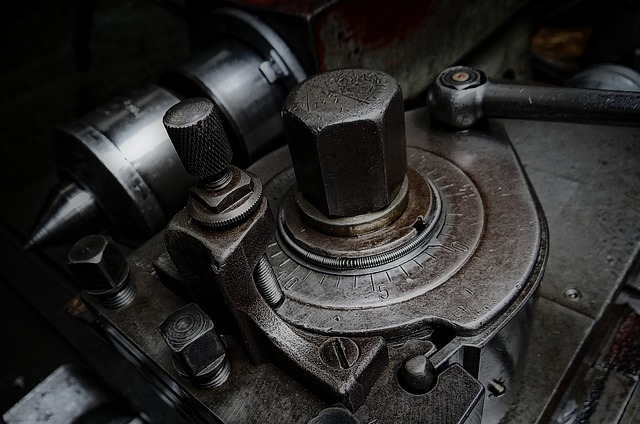
Haas lathes are built for repeatable precision and high-speed metal removal in industrial settings. They represent a cornerstone of modern turning operations where accuracy, control stability, and efficient tool management define productivity.
Precision Turning, Threading, and Contouring Operations
A haas lathe typically handles cylindrical components requiring threading or contouring with sub-micron repeatability. Its servo-driven axes maintain consistent tolerance bands even during complex multi-pass cycles. Operators rely on these machines for both roughing heavy stock and finishing intricate geometries such as valve stems or aerospace fittings.
G-Code-Based Programming Compatibility
The Haas control platform interprets standard G-code syntax used across CNC systems. This allows it to receive instructions from multiple CAM sources without proprietary formatting barriers. However, the structure of the code must reflect turning logic—commands like G96 (constant surface speed) or G71 (roughing cycle) differ from router commands common in Vectric outputs.
Integration Through Post-Processing
Bridging Haas controllers with non-lathe CAM tools depends heavily on post-processing scripts that translate toolpath data into valid command sequences. Without this translation layer, feed rate calls or spindle orientation codes may be misread by the controller, leading to motion errors or tool crashes.
Core Functions of Vectric CNC Software in Workflow Design
Vectric’s suite—VCarve Pro, Aspire, Cut2D—is widely used among woodworkers and light manufacturers for routing operations on flat materials. Its core design philosophy emphasizes simplicity and visual feedback rather than multi-axis kinematics.
Focus on 2D and 2.5D Routing Operations
Vectric generates toolpaths primarily suited for planar surfaces where depth changes occur incrementally rather than continuously around a rotating axis. This makes it ideal for sign-making, cabinetry panels, or relief carvings but less so for symmetrical turning tasks.
Toolpath Generation Optimized for Routers
The algorithms behind its toolpath generation assume linear feed motion along X-Y axes while maintaining Z as a depth parameter. Consequently, its cutting strategies—pocketing, profiling, drilling—are optimized for routers that clamp stationary material rather than spinning workpieces.
Output Formats Based on Milling Post-Processors
Most Vectric post-processors output code formatted for milling centers or gantry routers using Cartesian coordinates. These files require significant adaptation before being accepted by a haas lathe controller expecting polar coordinate input tied to spindle rotation.
Evaluating the Technical Integration Pathways
Integrating these two systems demands more than file conversion; it requires an understanding of motion logic differences between subtractive platforms. The process often involves developing custom post-processors and testing communication consistency between software layers.
Post-Processor Adaptation for Haas Lathe Use
A custom post-processor can map router-style moves into rotary equivalents recognized by the Haas control unit. Engineers must redefine axis references so that what was once an X-Y cut becomes an X-Z motion synchronized with spindle rotation. Adjustments also include spindle orientation handling (M03/M04) and proper offset registration using G54-G59 work coordinates.
Communication Between Software and Controllers
File transfer usually occurs via USB drives or Ethernet networks directly connected to the machine’s control interface. Each file must be verified through syntax checking within Haas’s editor since router-oriented commands may trigger alarms if unrecognized. Simulation within both environments helps confirm safe execution before material engagement.
Coordinate System Alignment Requirements
For reliable machining results, both systems must share a consistent coordinate origin reference. A mismatch—even by millimeters—can cause off-center cuts or wasted blanks. Establishing a unified datum point across CAD design, CAM processing, and machine setup prevents cumulative alignment drift during production runs.
Identifying Workflow Limitations and Optimization Strategies
Even with technical bridges in place, conceptual differences between routing and turning remain significant obstacles. The physics of chip formation change entirely when material rotates instead of the cutter moving linearly across it.
Differences Between Routing and Turning Toolpaths
Routing assumes fixed material under moving cutters; turning reverses that relationship. On a haas lathe, the workpiece spins while tools advance along controlled paths defined by revolved geometry profiles. Translating planar toolpaths into rotational equivalents requires recalculating feed per revolution instead of feed per minute values common in routers.
Redefining Toolpath Logic for Rotational Cutting
When adapting Vectric outputs to turning applications, programmers must reinterpret contour passes as radial engagements around a centerline rather than planar offsets from an edge boundary. Failure to adjust this logic leads to inconsistent diameters or tapered finishes across parts.
Feed Rate Optimization Differences
Because chip load depends on spindle RPM rather than linear velocity alone, feed rates need recalibration using formulas specific to cutting inserts’ nose radius and material hardness. Excessive feed per revolution can increase vibration risk; too low causes rubbing instead of cutting efficiency.
Adjusting Tool Libraries and Machine Parameters
Once translation pathways are confirmed functional, attention shifts toward refining physical parameters defining each operation’s stability and quality outcome.
Modifying Tool Definitions Within Vectric
Tool libraries originally designed for end mills must be redefined to represent lathe inserts including their rake angles, tip radii, and holder geometries. This change allows simulation previews to reflect realistic contact points between insert edges and rotating stock surfaces.
Recalibrating Spindle Speed and Feed Settings
Lathe operations depend on maintaining constant surface speed relative to diameter changes during cuts—a principle routers rarely apply. Operators should calculate RPM dynamically based on part diameter using built-in G96 commands rather than static S-values typical in milling files.
Minimizing Wear Through Correct Setup
Properly tuned feeds reduce flank wear on carbide inserts while improving surface finish uniformity across sequential batches. Documented parameter baselines also simplify repeat jobs where consistent dimensional accuracy is critical over time.
Exploring Alternative CAM Solutions for Hybrid Environments
While adapting Vectric outputs is possible technically, dedicated CAM platforms often deliver more robust integration with haas lathe systems out-of-the-box due to their native support structures.
When Dedicated CAM Systems Are Preferable
Software like Fusion 360 or Mastercam includes modules explicitly designed for multi-axis lathes supporting live tooling synchronization and automatic rough-finishing cycles. These programs generate validated post-processors maintained either by OEMs or active user communities ensuring compatibility updates align with firmware revisions from Haas Automation Inc.
Combining Vectric With Other CAD/CAM Tools
In hybrid workflows designers may still prefer Vectric’s intuitive modeling features before exporting geometry as DXF or STEP files into advanced CAM suites handling final toolpath generation tailored specifically for turning centers. This layered approach retains creative flexibility while maintaining mechanical precision downstream.
Data Exchange Through Standardized Formats
Using neutral exchange standards simplifies collaboration between departments running different software ecosystems without risking geometry distortion during conversions—a common issue when proprietary file types interact unpredictably across platforms.
Practical Considerations for Implementation in Production Settings
For manufacturers scaling mixed workflows involving both routers and lathes under one digital pipeline structure consistency becomes vital across every step—from concept modeling through final inspection reports.
Workflow Validation Via Simulation Tests
Running simulations inside both environments confirms synchronization between programmed speeds feeds coolant activations tool changes etc prior to physical machining reducing scrap costs significantly especially during prototype phases where setup times dominate budgets compared against actual run durations measured later under load conditions typical within batch series operations at scale factories worldwide today rely heavily upon such dry-run verification loops before committing expensive billets onto spindles spinning thousands rpm continuously shift after shift nonstop reliability demanded here cannot tolerate oversight period full stop
Establishing Repeatable Data Pipelines Between Stages
Naming conventions standardized coordinate origins plus automation macros converting output formats streamline transitions minimizing manual editing errors known cause downtime among cross-platform shops integrating routing plus turning simultaneously maintain discipline documentation prevents drift ensures reproducibility vital regulatory audits traceability requirements increasingly strict aerospace medical automotive sectors alike
Maintaining Process Documentation For Continuous Improvement
Recording integration parameters version histories feedback loops linking machinists programmers engineers fosters iterative refinement cycle boosting throughput gradually over months small gains accumulate measurable productivity leaps observed statistically industry benchmarking surveys confirm disciplined recordkeeping correlates directly reduced defect rates improved uptime ratios overall equipment effectiveness metrics trending upward consistently across digitally mature plants globally
FAQ
Q1: Can Vectric software directly run a haas lathe?
A: Not natively; it requires custom post-processing since default outputs target routers not turning centers controlled via spindle-based axes logic differences substantial need adaptation first
Q2: What risks occur when using incorrect post-processors?
A: Incorrect posts may generate invalid G-codes causing unexpected axis moves collisions alarms risking damage tooling fixtures sometimes entire machines if unchecked prior simulation step skipped
Q3: Is Fusion 360 better suited than VCarve for haas lathes?
A: Yes because Fusion includes dedicated lathe modules supporting full axis synchronization constant surface speed calculations adaptive roughing cycles unavailable inside standard VCarve environment
Q4: How can mixed workflows benefit small shops?
A: Combining router-friendly modeling within Vectric alongside precision-turning programming external CAM reduces software learning curve preserves creative flexibility without hardware conflicts common otherwise
Q5: Why is simulation mandatory before real cutting?
A: Because even minor coordinate mismatches between design file origin machine zero point lead catastrophic errors costly scrap potential operator safety hazards simulation catches anomalies early safeguarding both assets productivity