
How Does Depth Of Cut In Machining Influence Tool Deflection And Precision
What Is the Relationship Between Depth of Cut and Tool Deflection?
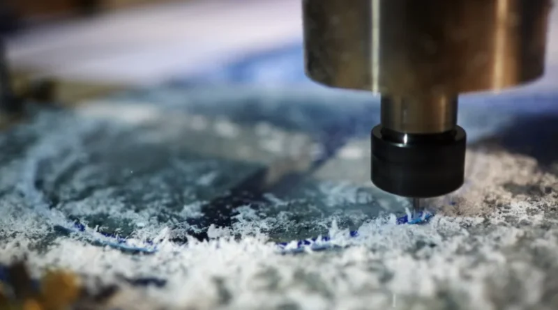
In machining, the depth of cut directly affects how a cutting tool acts under pressure. When you raise the depth, the cutting forces go up. Even a strong tool starts to bend a bit. This small bend might look tiny. But in exact work, it can ruin the size accuracy. Knowing how depth links with tool strength, material traits, and machine firmness helps you handle both speed and quality. For example, in a shop making car parts, ignoring this can lead to scrap pieces that cost extra time to fix.
The Mechanical Response of the Cutting Tool Under Load
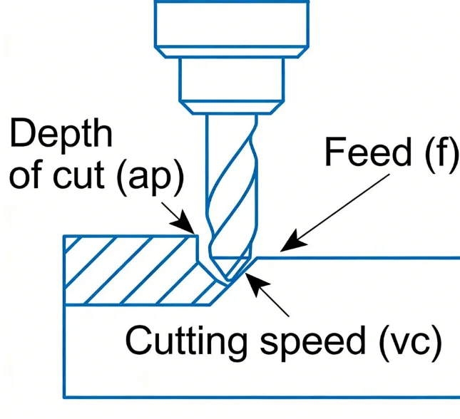
When the depth of cut grows, the cutting edge faces bigger side and front forces. These forces make the tool body bend a little. How much it bends relies on the tool’s shape. Long thin tools bend more than short thick ones. The tool material’s strength sets how well it fights the bending pull from cutting loads. In real jobs, if you double the depth, deflection often jumps more than twice. This happens because side and front forces both get stronger at the same time. That’s why deep cuts can twist part shapes, even with top tools. Think of milling a deep slot; without care, the walls end up uneven.
The Influence of Material Properties on Deflection Behavior
Various materials react in their own ways to cutting stress. Tough workpiece stuff like titanium alloys or hard steels push back harder at the cut spot. This boosts the bend forces on your tool. On the other hand, tool materials with a high bend resistance, such as tungsten carbide, handle these stresses better than high-speed steel. Coatings like TiAlN boost heat hold and cut down slide at hot spots. They help keep bending low under heavy work. Tweaking the inner structure through heat or tiny grain fixes spreads stress evenly over the cutting edge. In practice, I’ve seen carbide tools last longer in tough jobs, saving money on swaps.
The Role of Machine Tool Rigidity in Managing Deflection
Even with a perfect tool, the machine’s firmness matters a lot in keeping deflection in check. The machine’s build strength decides how much shift happens under big loads in deep cuts. Spindle bearings with tight setup cut down wobble and shake that make deflection worse. Good holding setups stop the workpiece from moving. This avoids fake or extra bending looks. Engineers often check dynamic strength to guess how depths will change system acts before making real parts. For instance, on a CNC mill, a shaky base can double the error in a 5mm deep pass.
How Does Depth of Cut Affect Dimensional Accuracy in Machining?
The depth of cut in machining changes more than just speed. It shifts shapes at a tiny level. Each bit of bend moves your real cut path. This brings size mistakes if you don’t fix it right.
Geometric Deviations Caused by Tool Deflection
Bending from stretch changes where the cutting edge touches the workpiece. It doesn’t stick to the set path. Instead, it shifts a tad in or out based on force pull. This makes smaller circles in turning or slanted sides in mill holes. Sometimes, wavy lines show up from changing shifts during the push. Many workers fix this with size tweaks or pre-set fixes in CNC codes. In a real case, like turning a shaft, a 0.1mm bend can push the diameter off by 0.05mm, failing tight specs.
The Impact on Surface Finish and Microgeometry
With bigger depths, shake chances rise a lot. This is because chip bite and touch area both grow. The outcome is chatter, a shake that builds on itself. It leaves clear marks on the surface. Roughness numbers like Ra and Rz climb fast in shaky spots. Cutting depth a touch often steadies the cut and brings back even feel on surfaces. For fine work like mold ends or plane parts, keeping small steady depths gives smoother tiny shapes without extra rub. Interestingly, in aluminum jobs, a 2mm depth might chatter, but 1.5mm runs smooth as glass.
Measurement and Correction Techniques for Dimensional Errors
New tools use on-the-go measure gear like laser eyes or touch sticks to spot shifts while cutting goes on. Live info lets auto fixes for guessed bend mistakes through smart CAM steps in CNC brains. These smart fixes hold tight sizes even when things like heat change in long jobs. Workers in high-tech shops swear by these for keeping runs error-free day after day.
Why Does Increasing Depth of Cut Elevate Cutting Forces and Stress Distribution?
When you push depth of cut past normal, both push load and heat jump sharp. The tie between chip size and force build is key to watch. Too much stress can wear out your tools fast.
The Relationship Between Chip Load and Force Generation
A deeper cut pulls more stuff per turn or push. This lifts the side force along the cut plane and side push on the cutter. These together loads change hot stress spots near the edge where tiny cracks start. Changing push speed with bigger depth spreads load even. It stops quick jumps that wear tools early. For steel bars, matching feed to a 3mm depth keeps forces steady around 500N, avoiding breaks.
Thermal Effects Induced by Higher Cutting Loads
As forces build, rub heat piles up where tool meets workpiece. High heat softens both locally, mainly if coolant lacks. This leads to more bend from heat grow. The mix effect cuts shape truth even if strength stays the same. Strong spray coolant or tiny oil mist setups hold steady heat lines in deep work. In hot shops, bad cooling can add 20% more deflection from heat alone.
Stress Propagation Within the Tool Structure
Stress moves along the stem and groove parts based on shape and push way. Thin tools catch tiny bends that add up to seen shape flaws on done parts. Over and over stress speeds wear from tiredness around curves or thin spots where size drops quick. Computer shape models let engineers see these stress trails before real tests. It’s like mapping a road before driving; spots weak turns early.
How Can Depth of Cut Optimization Improve Machining Precision?
Finding the right balance between speed and exactness means picking a best depth of cut in machining. It cuts mistakes without losing work rate. Sometimes, trial runs show the sweet spot varies by shop setup.
Balancing Material Removal Rate with Dimensional Control Requirements
Each task has a good point where pull rate fits size needs well. Too light, and times drag slow. Too heavy, and truth falls quick from more bend and shake risk. Planners use past job facts plus computer runs to set this point right for each stuff-tool match. In a factory run, aiming for 10mm³ per second often hits both goals without fuss.
Adaptive Control Systems for Real-Time Adjustment of Cutting Parameters
Smart plants use feelers near spins or holds that watch live signs like shake size or spin pull changes. These bits feed brainy controls that tweak push speed or depth on the fly when trouble starts in a cut round. Such smart watch cuts hand watch and boosts same results over many batches. It’s handy for long shifts where things heat up unevenly.
Integration of Predictive Models in Process Planning
Guess tools run how depths will sway bend ways before any cut starts. Math rules guess stretch bend from inputs like tool long-to-wide rate or stuff bend values. Shape computer runs give sight into stress spread under different spots. Using these early in plan stops pricey try-fix later on floors. One engineer noted it shaved 30% off setup time in prototype work.
What Are the Practical Strategies to Minimize Tool Deflection at Varying Depths of Cut?
Cutting bend needs mixing wise pick choices with steady run sets. Don’t bank on just one thing like tool strength. Real-world tweaks, like in auto repair shops, often mix these for best results.
Selection of Optimal Tool Geometry and Material Composition
Picking tools with wider rounds boosts firmness. Bend fight grows fast with size area. Strong stems cut shake pass along long hangs common in hole mill jobs. Stuff like cemented carbide gives better bend hold than old steels. It keeps wear fight under heavy pulls for deep runs. A 12mm end mill, say, deflects half as much as an 8mm one at 4mm depth.
Implementation of Supportive Fixturing Systems
A firm hold setup stops workpiece shift that could grow seen bends in cut rounds. Soft pads under clamp spots soak leftover shakes from spotty touch between teeth and bumps. Swap hold systems let quick change without losing build firmness when part shapes switch often. In batch work, this keeps parts steady, avoiding 0.02mm drifts.
Process Parameter Adjustment for Stable Machining Conditions
Tweaking run settings is one easy but strong way to control bend acts over different depth picks. Dropping push rate a bit cuts quick load hits while keeping steady chip shapes for clean ends. Splitting full pull into small layers spreads push power even over next passes. This works well for thin wall parts that twist easy. For a 10mm wall, two 2mm passes beat one 4mm dive.
FAQ
Q1: What happens if I exceed recommended depth limits?
A: You’ll likely experience excessive tool bending leading to dimensional inaccuracies and poor surface finish due to chatter formation.
Q2: How do I detect tool deflection during production?
A: Monitoring spindle load variations or using displacement sensors provides early indicators before visible defects occur.
Q3: Can software predict optimal depth automatically?
A: Yes, modern CAM platforms integrate predictive algorithms that simulate force distribution versus depth profiles prior to execution.
Q4: Which materials are most sensitive to deflection issues?
A: Hard-to-machine alloys like Inconel or titanium amplify reaction forces significantly compared with aluminum or mild steel substrates.
Q5: Does coolant type affect deflection control?
A: Absolutely; efficient cooling lowers interface temperature gradients thereby reducing thermally induced expansion contributing indirectly toward minimizing overall tool deviation.