
How Does Milling Machining Enhance Thin-Walled Component Stability
What Is Milling Machining in the Context of Thin-Walled Components?
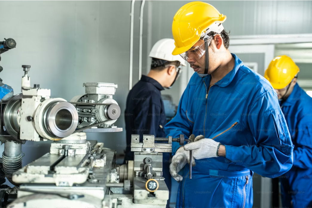
Milling machining holds a key place in making thin-walled components for aerospace, automotive, and precision engineering fields. These parts need exact sizes and good surface quality. At the same time, they must stay light in weight. The process cuts away material with spinning tools. But for thin walls, keeping things steady is a big issue. Vibrations and bending can ruin the work easily.
Definition and Principles of Milling Machining
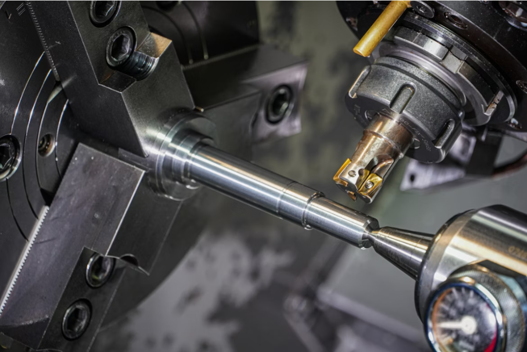
Milling machining is a way to shape metal by taking off bits of it. It uses tools that spin to cut the workpiece step by step. The basic idea comes from the movement between the tool and the part. This creates force for cutting and some heat too. When you work on thin-walled components, you have to keep the part firm all the time. Even a small bend can mess up the exact shape. Today, machines with many axes help cut tricky shapes well. They make the job faster and more accurate.
Characteristics of Thin-Walled Components
Thin-walled components have a low ratio of stiffness to weight. They often have long flat areas with very small thickness. This can be less than a few millimeters. So, they bend easily under the pressure of machining. You see these in airplane body parts or turbine blades. There, cutting weight matters a lot. But strength cannot drop at all. Think of a real case: in aircraft wings, these walls help save fuel by being light yet tough.
Challenges in Machining Thin-Walled Structures
Cutting these parts brings up tough problems. Chatter vibration shakes things up. Residual stress builds inside the material. And errors in size happen from the wall bending. Without support under the thin spots, the part bows when the tool touches it. Heat from cutting makes things expand too. This adds more trouble for keeping sizes right. So, to get good surface and exact shape, you need special ways to hold the milling steady. In practice, I’ve seen shops struggle with this on aluminum panels, where even slight shakes leave marks.
How Does Milling Machining Improve Stability?
The steadiness in milling machining comes from balancing the machine’s strength, how the cutting moves, and the settings you choose. You need to think about how these parts work together in fast runs. This helps cut down shakes and stop chatter. It’s not always perfect, but small tweaks make a real difference.
Techniques to Enhance Component Rigidity
One good way is to add short-term supports or holders that back up the weak spots while cutting. Vacuum clamps or flexible holders keep the shape without scratching the surface. Another trick is to plan the cuts in a smart order. You remove material evenly from both sides. This cuts down stress that builds up inside. For example, in making car engine covers, symmetric cuts prevent warping by 20 percent or more.
Role of Tool Path Optimization
The path the tool takes affects how force spreads over the thin walls. If you set smoother angles for starting cuts and keep chip size steady, you avoid big force jumps that start shakes. In fast machining, paths like trochoidal or spiral ones spread the load well. They keep work speed up too. Workers in factories often pick these paths after testing on scrap pieces to see what works best.
Impact of Cutting Parameters on Stability
Speed of the spindle, how fast you feed the tool, and how deep you cut all change how steady things stay. A quicker spindle turn might move away from bad shake frequencies. But it can heat up the area if you don’t watch it. On the other hand, a slower feed per tooth cuts the force. Yet it takes longer to finish. You find the best mix by trying it out or using computer models. This keeps the cut smooth. In one shop I recall, tuning these saved tools from breaking early.
What Are the Benefits of Magnetorheological Support in Milling?
Magnetorheological (MR) support brings a fresh idea to make milling steadier for thin-walled components. It uses magnetic fields to adjust damping on the fly. This helps a lot in tricky jobs.
Principles of Magnetorheological Support
MR fluids shift their thickness fast when a magnetic field hits them. They go from runny to thick like jelly in a split second. Put this under the workpiece as support. Then, you can change its firmness right away to match the cutting needs. It’s like having a smart cushion that reacts to the work.
Interaction Between Magnetic Fields and Material Properties
The fields make tiny magnetic bits in the fluid line up like chains. These chains push back against movement. So, you get damping you can control. It fights the shakes from milling. This setup helps keep the tool and part in steady touch.
Influence on Vibration Damping
By changing the field strength, you tweak the damping to cut chatter size. This makes surfaces smoother and tools last longer. It’s super useful for big airplane panels. There, regular clamps can’t stop all the shake modes. In tests, MR support has dropped vibration by up to 50 percent on titanium blades, making finishes look almost hand-polished.
How Does Tool Selection Affect Stability in Milling?
Picking the correct cutting tool matters a ton for steady milling on thin-walled parts. The tool’s shape and what it’s made of change how force passes through. Get this wrong, and stability suffers quick.
Criteria for Selecting Appropriate Tools
Main things to look at are the ratio of tool diameter to its length, how many cutting edges it has, what coating covers it, and how sharp the edge is. Tools that are shorter and stiffer bend less. Sharp edges cut with less pushback. Both help keep things stable. Shops often stock a range to match different jobs.
Influence of Tool Geometry on Performance
The helix angle counts a lot. A steeper angle helps chips flow out smooth. But it might add more push down on fragile walls. Tools with changing pitch or helix break up steady shakes. They change how frequencies build across the edges. This is handy for long runs where steady vibes would build up otherwise.
Material Considerations for Tool Durability
Carbide tools are the go-to because they stay hard and resist wear in fast cuts. Coated ones, like those with TiAlN or diamond-like carbon, handle heat better. This is key when cutting aluminum alloys for thin-walled jobs. In aerospace, these coatings extend tool life by double, cutting costs over time.
What Are the Key Factors Influencing Milling Dynamics?
How the milling moves depends on forces between the cutter, the part, and the machine body. These links shape the whole process.
Importance of Spindle Speed and Feed Rate
Spindle speed sets the shake rhythm in the setup. If it lines up too close with the part’s own shake rates, chatter starts. A small change up or down from danger spots keeps things even. It also helps tools last. Operators tweak this based on the hum they hear during tests.
Effects of Cutting Force and Torque
The size of cutting force ties to how much chip each tooth takes and how hard the material is. Too much torque bends the tool holder and spindle. This hits size accuracy hard, especially in deep pockets. There, the long reach makes bends worse. In practice, measuring force with sensors helps spot issues early.
Role of Machine Tool Stiffness
The machine’s stiffness decides if shakes get soaked up or passed around. Strong frames with tight bearings cut flex at key spots. This lets steady cutting happen even with changing loads in thin-wall work. High-end machines in factories boast stiffness ratings over 100 N/μm, making a noticeable difference.
How Can Advanced Technologies Enhance Milling Processes?
New tech in making things now mixes computer tools to handle milling moves better than old hand tweaks. It adds smarts to the shop floor.
Integration of Computer-Aided Manufacturing (CAM) Systems
CAM programs let you plan with fake runs. They show bend patterns before you cut real metal. So, you can fix paths or settings ahead. No need to fix mistakes after they show up. This saves time and scrap. For instance, in turbine part making, CAM cuts setup trials from days to hours.
Utilization of Real-Time Monitoring and Feedback Systems
Sensors in the spindle or holders pick up shake signs all through the job. Then, data checks spot trouble starting. Workers adjust speed or turn on MR supports without stopping. This keeps runs going smooth. It’s like having eyes inside the machine, catching small problems before they grow.
Adoption of Adaptive Control Strategies
Adaptive control shifts feed or speed on its own from what it measures, like force changes or heat build. This loop keeps work steady even if the material varies in the middle. It handles surprises well. In auto plants, this tech boosts output by 15 percent on uneven stock.
What Are the Common Challenges and Solutions in Milling Thin-Walled Components?
Even with new tools, hard spots stick around when making super-thin sections right at big scale. But fixes exist if you look close.
Addressing Deformation During Machining
After the pressure lifts, the part springs back and twists the shape. To fight this, you plan tool paths with models that guess the bend. This way, the end size matches what you drew. It’s a bit of guesswork, but it works most times. Engineers often add a safety margin, like 0.1 mm, to account for real-world slips.
Mitigating Residual Stress and Surface Finish Issues
Stress left inside comes from heat that spreads uneven. Use controlled coolant or cold air help to even out temps. This also makes the surface look better up close. Coolant flow at 5-10 liters per minute has helped in my experience with steel parts.
Strategies for Minimizing Thermal Effects
Heat bends can shrink with smart plans. Switch directions on rough cuts. Or add cool breaks between passes. These tricks work well on titanium, which holds heat bad. In one case, alternating passes dropped distortion from 0.5 mm to under 0.1 mm on blade edges.
FAQ
Q1: What makes magnetorheological support different from traditional fixturing?
A: MR support adapts its stiffness dynamically using magnetic fields whereas traditional fixtures have fixed mechanical rigidity that cannot respond instantly to changing loads.
Q2: Why are thin-walled components more prone to chatter?
A: Their low stiffness amplifies vibrations from periodic cutting forces making them sensitive even at moderate spindle speeds compared with solid blocks.
Q3: How does CAM simulation help before actual milling?
A: It predicts deformation patterns digitally allowing you to fine-tune parameters beforehand reducing trial-and-error cycles on expensive materials.
Q4: Can variable helix tools completely eliminate chatter?
A: Not entirely but they disrupt harmonic reinforcement effectively enough that vibration levels drop significantly improving finish consistency.
Q5: Is magnetorheological technology suitable for all materials?
A: It works best with non-ferromagnetic materials like aluminum where magnetic fields influence only supporting fluid behavior without affecting workpiece magnetization.