
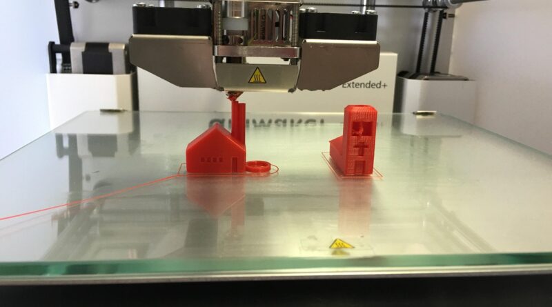
Prototype machining guide for functional CNC parts
What prototype machining means in CNC manufacturing
Prototype machining uses CNC milling, turning, drilling and related subtractive processes to make one-off or low-volume parts directly from engineering materials. For product teams, the value is not only speed. A machined prototype can be used to check form, fit, strength, sealing surfaces, threaded features, heat resistance and assembly behavior in a material that is often closer to production than a visual prototype. Within the broader CNC machining workflow, prototype parts usually sit between early concept models and repeatable production runs.
Manufacturing references from organizations such as NIST describe CNC machining as one route for producing small quantities without dedicated tooling. That makes prototype machining useful when the design is still changing, when a part must be evaluated under load, or when the team needs a machined datum structure before committing to molds, castings, die-cast tooling or fixtures.
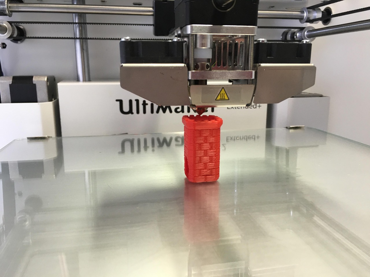
The practical question is not whether machining is always better than 3D printing, sheet metal or molding. It is whether the prototype needs to behave like a cut metal or engineering plastic part. If it does, CNC machining usually gives designers a more direct way to gather functional evidence.
When CNC prototype machining is the right choice
CNC prototype machining is strongest when material behavior, dimensional control or surface quality matters more than the lowest possible first-part cost. A machined aluminum housing, stainless bracket, acetal gear blank or PEEK insulator can support tests that a cosmetic polymer print may not. Machined parts can include tapped holes, bearing seats, precision bores, counterbores, flat sealing faces and repeatable datums.
It is also useful when the final production method is not yet fixed. A machined prototype can validate geometry while the team is still comparing casting, molding, extrusion, fabrication or additive manufacturing. In many programs, machining is used to answer design questions before the company spends money on hard tooling.
| Prototype need | Why machining can help | Main caution |
|---|---|---|
| Functional fit check | Machined datums and holes can represent assembly interfaces clearly. | Do not tolerance every non-critical face as if it were an interface. |
| Load or wear testing | Parts can be cut from production-like metals or engineering plastics. | Machined grain direction and stock form may differ from cast or molded production parts. |
| Thermal or chemical exposure | Material options include aluminum alloys, stainless steels and high-performance plastics. | Confirm that the exact grade, temper and finish match the test objective. |
| Pre-tooling validation | No dedicated mold or die is required for a small batch. | A machined prototype may not reproduce draft, ribs or shrinkage from molded production. |
Machining is less attractive when the prototype has internal channels that cutting tools cannot reach, lattice geometry, very thin unsupported walls, or organic surfaces that would require long 5-axis surfacing time. In those cases, additive manufacturing may be a better first proof of shape, followed by machining for the features that need dimensional control.
The prototype machining workflow from CAD to inspected part
A good prototype machining workflow starts before a quote request is sent. The CAD model should identify the intended material, the critical interfaces, and the surfaces that do not justify tight control. When every feature appears equally critical, the shop has to price the risk into the job or ask for clarification.
Define the purpose of the prototype
Before choosing tolerances or finishes, define what the prototype must prove. A visual review part calls for different decisions than a prototype used for fatigue testing or sealing validation. A single machined part for an investor demo may place more emphasis on appearance, while a batch of 20 parts for engineering testing may require repeatability and inspection records.
Prepare the CAD model and drawing together
Modern machining often starts from a 3D model, but a model alone usually does not communicate all manufacturing intent. A simple 2D drawing is still valuable for material callouts, finish requirements, general tolerances, critical dimensions, threads, datums and inspection notes. Standards such as ASME Y14.5 for GD&T and ISO general tolerance references are commonly used to reduce ambiguity, although the specific standard must be agreed by the buyer and manufacturer.
Plan setups, workholding and tool access
Prototype cost often rises when a part needs several setups, custom soft jaws, long-reach tools or reorientation to reach features on multiple faces. A 5-axis machine can reduce setup changes for some geometries, but it is not a universal shortcut. Simple 3-axis milling or turning may be faster and less costly for prismatic brackets, plates, spacers and shafts.
Tolerances, GD&T and inspection decisions
Tolerance strategy is one of the clearest differences between a useful prototype and an expensive experiment. Many digital machining suppliers publish default machining tolerances around plus or minus 0.005 in. or about plus or minus 0.1 mm for standard work, but those figures are supplier policies, not universal CNC capability. Actual achievable tolerance depends on feature size, material, geometry, machine condition, workholding, thermal stability, tool wear and inspection method.
The practical approach is to tolerance only what the prototype must prove. A bearing bore, shaft fit, gasket surface, dowel hole pattern or optical mount may need tight control. A clearance pocket, outside cosmetic wall or non-mating underside may not. Over-tolerancing non-critical geometry can add machining time, inspection time and rework risk without improving the test result.
| Feature type | Typical prototype concern | Practical control method |
|---|---|---|
| Datum faces | Assembly reference and inspection repeatability | Identify primary, secondary and tertiary datums on the drawing. |
| Bores and bearing seats | Fit, concentricity and surface finish | Use explicit size tolerance and GD&T where function requires it. |
| Threaded holes | Depth, engagement and tool access | Specify thread standard, depth and whether inserts are acceptable. |
| Thin walls | Deflection, chatter and warpage | Relax cosmetic requirements or increase wall thickness where possible. |
| Sealing faces | Flatness, finish and gasket compression | Call out finish and flatness only on the actual sealing area. |
Inspection should match the prototype risk. For a rough fit-check part, a basic dimensional report may be enough. For a prototype that supports design release, first article inspection, CMM measurement or documented material certification may be appropriate. The key is to request the inspection level before manufacturing, not after a part fails a late-stage test.
Material and finish choices that affect performance
Material selection should follow the prototype objective. Aluminum 6061 is widely used for machined prototypes because it cuts well, offers good strength-to-weight performance and can be anodized. Aluminum 7075 may be chosen when higher strength is needed, but it can change cost and finish decisions. Stainless steels are useful for corrosion resistance and strength, while brass and some copper alloys can support electrical, thermal or wear-related tests.
Engineering plastics need particular care. Acetal, nylon, polycarbonate, PTFE and PEEK can all be machined, but plastics may move with heat, moisture and clamping pressure more than metals. Thin plastic walls can warp after machining as stresses are released. If the prototype is intended to validate molded plastic behavior, the team should remember that a machined billet part may not reproduce molded fiber orientation, sink, knit lines or shrinkage. See also: CNC Programming.
Finish decisions also affect cost and schedule. Deburring is usually expected, while cosmetic finishing, bead blasting, anodizing, passivation, plating and polishing add process steps. For early engineering builds, it may be better to keep finishes functional and reserve cosmetic requirements for a later design freeze. If a finish affects dimensions, corrosion resistance or electrical continuity, it should be specified clearly rather than treated as decoration.
Design choices that reduce prototype cost and lead-time risk
Many prototype machining delays come from preventable design ambiguity or geometry that works against the process. Deep narrow pockets require long tools that can chatter. Sharp internal corners require small cutters or secondary operations because rotating tools naturally leave radii. Very deep holes, hidden undercuts and complex blended surfaces can require nonstandard tooling or EDM. These features are not impossible, but they should be used only when the function justifies them.
- Use realistic internal radii. Larger inside corner radii allow stronger tools and faster cutting. If a sharp internal corner is not functional, avoid it.
- Separate critical and non-critical surfaces. Tighten only the dimensions that affect fit, sealing, motion, safety or test validity.
- Keep wall thickness reasonable. Thin walls can deflect during cutting and move after unclamping, especially in plastics and large aluminum parts.
- Design around tool access. If a cutter, drill or tap cannot reach a feature from a practical setup direction, cost and risk increase.
- Use standard stock and hardware where possible. Standard material sizes, thread forms, inserts and fasteners reduce avoidable special handling.
- Clarify surface finish only where it matters. A global fine finish callout can raise cost even when only one mating face needs it.
A useful design review question is whether each feature teaches the team something. If a tight tolerance, finish or difficult pocket does not answer a functional question, it may belong in a later prototype rather than the first machined build.
How prototype machining compares with 3D printing and tooling
Prototype machining and 3D printing often work best together rather than as direct rivals. Additive manufacturing can quickly show shape, packaging and ergonomic intent, including complex internal forms that are hard to machine. Machining can then validate the surfaces, fits and material behavior that must survive functional testing. NIST additive manufacturing guidance describes AM as an alternative to machining, forging, molding and casting for customized parts, while also noting measurement and qualification challenges for critical components.
Compared with injection molding, prototype machining avoids the time and cost of dedicated tooling. That is valuable when geometry is still changing. However, machined prototypes do not automatically predict molded-part issues such as draft constraints, gate marks, shrinkage, sink, weld lines or fiber orientation. A sound development plan may use machining to validate mechanical interfaces, then use prototype tooling or bridge tooling to validate the actual molding process.
Compared with casting or forging, machining from billet can provide faster early evidence, but it may not represent final microstructure or near-net-shape economics. For safety-critical or regulated products, a machined prototype should not be treated as production validation unless the material form, process route and inspection plan match the final requirements.
Practical checklist before ordering machined prototypes
- Confirm the prototype purpose, such as fit check, load test, thermal test, customer review or pre-production validation.
- Specify material grade, temper or condition, and any acceptable substitutes.
- Provide a clean CAD model and a drawing for tolerances, datums, threads, finishes and inspection needs.
- Mark critical-to-function features instead of applying tight tolerances everywhere.
- Review wall thickness, internal radii, hole depths, pocket depths and tool access.
- Decide whether cosmetic finish matters for this build or can wait.
- Request the inspection report, material certification or traceability level required for the test.
- Document lessons from the first build so the next prototype is not just a repeat order.
The strongest prototype machining projects are not defined by the fastest spindle time. They are defined by clear intent. When the CAD model, drawing, tolerance plan and inspection method all support the same engineering question, a machined prototype can shorten design loops and reduce the risk of expensive tooling changes later.
Frequently asked questions
Is prototype machining only for metal parts?
No. CNC prototype machining is common for metals, but it is also used for engineering plastics such as acetal, nylon, polycarbonate and PEEK. The choice depends on what the prototype must prove. Plastic machining requires attention to clamping, heat and possible warpage.
What tolerance should I use for a CNC machined prototype?
Use the loosest tolerance that still proves the function. Tighten holes, datums, bearing seats, sealing faces and alignment features only when they affect performance. Supplier default tolerances can be a starting point, but critical features should be shown clearly on the drawing.
When should I choose 3D printing before machining?
Choose 3D printing first when the goal is quick visual review, ergonomic evaluation, packaging study or complex geometry that does not need production-like material behavior. Move to machining when the prototype must test strength, fit, threads, sealing, wear or thermal performance in a more representative material.
Can a machined prototype be used as a production part?
Sometimes, especially for low-volume equipment, fixtures, test rigs and specialty components. But if the final product will be molded, cast, forged or additively manufactured, a machined prototype should be treated as functional evidence, not complete production validation.
What information should be included in a prototype machining drawing?
Include material, units, general tolerance reference, critical dimensions, GD&T where needed, threads, surface finish requirements, datums, finish notes and inspection requirements. The drawing should make the functional priorities clear without over-controlling every surface.