
What Is Cutting & Tooling and How Do You Choose the Best Setup?
Why Does Cutting & Tooling Matter in Modern Manufacturing?
In a machine shop, cutting & tooling choices decide how the material comes off, how long the spindle keeps running, and how often an operator has to stop for a tool change. From the office, it may look like a small buying category: inserts, holders, cutters, drills, and taps. On the floor, it affects cycle time, scrap, finish, heat, noise, safety, and delivery dates. A worn insert late on Friday can hold up a whole order.
For export-focused manufacturers, tooling also affects how buyers judge day-to-day reliability. A customer may never ask which coating you used on a carbide end mill, but that customer will notice burrs, drifting tolerances, late shipments, or an uneven surface finish. Source context matters here: NIST Manufacturing Economics reported, in data available in 2026, that U.S. manufacturing accounted for about $2.3 trillion in value added and 10.2% of GDP, with $5.7 trillion in net stock. Cutting tools are a small item inside that large system, but they sit at the step where a drawing becomes a shipped part.
Tooling Turns Machine Power into Real Cutting
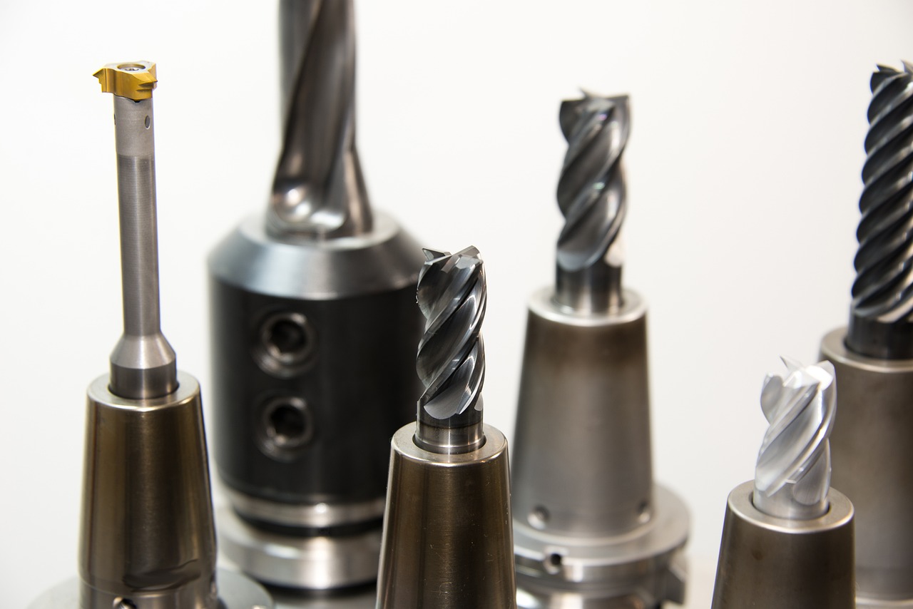
A CNC mill or lathe creates value only when the edge meets the material in a controlled way. The cutting tool takes that load every second it is in the cut. Geometry, grade, coating, holder runout, coolant access, and clamping rigidity decide whether the machine cuts cleanly or only makes heat and vibration.
Take a basic steel bracket as an example. The drawing may call for a milled slot, drilled holes, and a chamfered edge, and each feature asks for different tool behavior. The drill has to center well and move chips out. The end mill has to resist deflection. The chamfer tool has to leave a clean edge without chatter. Poor tooling can turn a simple part into rework.
Small Tool Changes Can Move Big Shop Metrics
Many shops look for bigger gains by buying new machines, but a tool change can be quicker and cheaper. A better chipbreaker may stop stringy chips in turning. A shorter holder may reduce chatter in a pocket. A high-feed cutter may rough a mold base faster with lower radial force.
The aim is not to buy the most expensive tool on the shelf. The aim is to match the tool to the job. If a $35 insert runs 40% longer on a repeat job, the saving may show up as fewer stops and steadier output, not just lower tool spend. That point is easy to miss when the quote sheet only shows unit price.
Cutting Choices Shape Customer Confidence
Buyers rarely see the tooling room, but tooling decisions show up in the part they receive. Burr level, hole size, thread quality, flatness, and surface texture all come from the cutting process. In regulated or high-precision supply chains, these details carry more weight.
When you can explain why a certain cutter, coating, coolant method, or inspection interval is used, you sound like a manufacturer that understands the job. That helps during RFQs, especially when buyers are comparing overseas vendors on more than unit price. It also gives the buyer more reason to trust repeat orders.
How Should You Match Cutting Tools to Workpiece Materials?
Material comes first. A cutting edge that works well in aluminum may fail quickly in stainless steel. A tool that cuts free-machining brass may rub in titanium. Before picking a tool, check the material family, hardness, heat treatment, part shape, and required finish. Then check machine power and clamping. The right answer is usually a set of choices, not one catalog line.
Aluminum Needs Sharp Edges and Chip Space
Aluminum usually needs sharp tools, polished flutes, high rake angles, and open chip space. Built-up edge can damage the finish, so low-friction coatings can help, though many shops still use uncoated or polished carbide for certain aluminum jobs. Chip evacuation is the main point. If chips recut in a deep pocket, the finish drops fast and the cutter starts to sound wrong.
For thin-walled aluminum parts, reduce cutting force before chasing speed. Use sharp geometry, balanced toolpaths, and modest radial engagement. A little care here can prevent wall chatter and size drift, which saves time at inspection.
Stainless Steel Rewards Heat and Feed Control
Stainless steel is harder to manage because it can work harden. If the feed is too light, the tool rubs, and the next pass has to cut a harder surface. That is why cautious cutting is not always safer cutting. A steady chip load, strong edge prep, and reliable coolant can make the process more stable.
Austenitic stainless grades often need positive geometry and enough feed to get below the hardened skin. In turning, chipbreakers matter because long stainless chips are sharp, hot, and hard to control. No operator wants to pull a bird’s nest out of a chuck.
Hardened Alloys Need Tough Grades and Stable Holding
For hardened steels, nickel alloys, and titanium, tool toughness matters as much as hardness. These materials raise cutting temperature and expose weak setups quickly. Use shorter overhang where possible, rigid holders, and cutters made for interrupted or high-load cutting.
Published machining research often shows the same basic pattern: cutting speed, feed, depth of cut, and tool geometry work together. A CIRP Journal of Manufacturing Science and Technology paper on high-speed pocketing discussed feed, speed, torque, power, and chatter limits as linked choices, not separate numbers. That fits normal shop experience. A parameter can look fine on paper and still fail when the holder, fixture, or machine is not ready for it.
Which Tool Geometry and Coating Choices Make the Biggest Difference?
Geometry cuts the material. Coating protects the edge. Grade keeps the tool working under load. If you only compare tool brand and price, you miss the details that matter in the cut. Corner radius, helix angle, rake, clearance, chipbreaker shape, flute count, substrate, coating thickness, and edge prep all change how the tool behaves.
Edge Geometry Sets the Cutting Feel
A sharp positive edge lowers cutting force and helps in soft materials or on lighter machines. A stronger honed edge lasts better in cast iron, interrupted cuts, and harder steels. Neither type is better in every case. The tool needs the right balance between sharpness and edge strength.
Corner radius also deserves attention. A larger radius can improve finish and tool life, but it may raise radial force and cause chatter on a weak setup. A small radius can reach fine details, but it may chip faster. If tolerance is tight, this small corner can become a real problem.
Coatings Control Heat, Friction, and Wear
Common coatings such as TiN, TiCN, TiAlN, AlTiN, DLC, and diamond-based layers each suit different work. Heat-resistant coatings often fit steel and high-temperature alloys. Low-friction coatings can help aluminum and gummy materials. Diamond coatings can work well in graphite and abrasive nonferrous materials, but they are not the normal choice for ferrous steel cutting.
Coating choice should follow the heat path in the process. In dry or near-dry milling, the coating has to handle temperature changes. In coolant-heavy drilling, lubricity and edge strength may matter more. If those conditions are mixed without thought, tool life can drop fast.
Chipbreakers Keep the Cut Predictable
Chipbreakers are not just shapes in a catalog. They form the chip, reduce tangling, and help keep the cut steady. For turning carbon steel, the right chipbreaker can change a long ribbon into tight sixes and nines. That is safer for the operator and easier for automation.
In drilling and boring, flute form and chip clearance do similar work. Deep holes need a clear path for chips to leave. If chips pack inside the hole, torque rises and the tool may seize. This is why peck cycles, through-tool coolant, and special drill geometry are used.
How Do Speeds, Feeds, and Tool Life Work Together?
Speeds and feeds are not magic numbers. They are starting points that need feedback from chips, sound, spindle load, finish, and tool wear. A catalog value is useful, but it cannot know your fixture, coolant concentration, machine age, or operator habits. Start there, then adjust the cut with real evidence from the machine.
Cutting Speed Drives Heat at the Edge
Cutting speed has a clear effect on heat. Higher speed can raise output, but it also speeds up wear when the tool grade or coolant plan cannot handle the heat. MIT OpenCourseWare machining teaching materials summarize classic cutting process relationships, including the link between cutting speed and tool wear. The old lesson still holds: speed helps, but it has a cost.
In milling, surface speed also changes with tool diameter. A small tool at the same rpm cuts much slower than a large tool. That is why rpm, tool diameter, and material have to be calculated together. Guessing by sound alone is risky, although experienced operators often hear trouble early.
Feed Rate Controls Chip Thickness
Feed decides how much material each edge removes. Too little feed can cause rubbing. Too much feed can overload the edge, break corners, or push the part out of position. For multi-flute tools, chip load per tooth is the number to watch, not only table feed. See also: CNC Machining.
Here is a shop-floor example. If a four-flute end mill runs at 6,000 rpm and the target chip load is 0.03 mm per tooth, the feed is 720 mm per minute. Change to a two-flute cutter and the same chip load gives 360 mm per minute. The machine display looks slower, but the cutting edge sees the same bite.
Depth of Cut Changes Force and Deflection
Axial and radial depth of cut decide how much of the tool is engaged. Heavy engagement raises material removal rate, but it also raises force, heat, and deflection. In roughing, a smaller radial cut with higher feed can sometimes beat a full-width cut because the tool runs cooler and steadier.
Tool life should be measured by useful parts, not only by minutes in the cut. If a cutter lasts longer but leaves burrs that need hand work, it may not be the better option. Count tool cost, cycle time, inspection results, deburring, scrap, and operator attention. That is the bill the shop actually pays.
What Role Do Tool Holders, Coolant, and Machine Setup Play?
A good cutter in a poor holder is like a good tire on a bent wheel. It may run, but it will not run well. Tool holding, coolant delivery, fixture stiffness, spindle condition, and machine alignment decide whether the cutting edge can do its job. Many tooling problems start outside the cutter itself.
Runout Shortens Tool Life Fast
Runout means one edge cuts more than the others. In milling, that edge wears first, and then the cutter loses balance and finish quality drops. In drilling, runout can make holes oversize, hurt roundness, and break drills. Small tools suffer most because a tiny offset is large compared with tool diameter.
Collets, shrink-fit holders, hydraulic chucks, milling chucks, and side-lock holders each have a place. For fine finishing and small tools, low runout is worth the extra cost. For heavy roughing, pullout resistance and rigidity may matter more. The holder should match the work, not just the tool shank.
Coolant Needs Direction, Not Just Volume
Coolant only works when it reaches the cutting zone. Flood coolant that bounces off chips may look active but do very little. Through-tool coolant, high-pressure coolant, mist systems, and air blast each solve different problems. The right choice depends on chip shape, material, hole depth, heat, and cleanliness rules.
For aluminum pocketing, air blast may clear chips better than weak flood coolant. For stainless turning, directed high-pressure coolant can break chips and cool the edge. For cast iron, dry machining may be acceptable if dust control and machine protection are handled properly. The coolant method should fit the cut, not just the machine standard.
Fixtures Decide Whether Parameters Hold
A cutting chart assumes the part stays still. Fixtures make that possible. Weak clamping allows vibration, size movement, poor finish, and tool chipping. Thin parts, castings, weldments, and long shafts need special care because they can move under cutting load.
Good fixtures support the part near the cut, leave room for chip flow, and allow repeatable loading. That last point matters in production. A setup that works only when one senior machinist loads the part in exactly the right way is too fragile for steady output.
How Can You Build a Smarter Cutting & Tooling Purchasing Plan?
Buying cutting tools only by unit price can look controlled, but it often hides waste. A cheaper insert may need more changes. A tool with a higher price may shorten cycle time or reduce scrap. A practical plan connects purchasing, programming, setup, quality, and safety. It does not need to be complex, but it does need to be clear.
Standardized Tool Data Cuts Confusion
ISO 13399 is a public international standard for cutting tool data representation and exchange. ISO describes it as covering key categories of cutting tool data and the relationships between them. In plain shop terms, it helps different systems describe tools, holders, and related items in a structured way.
This matters because wrong tool data creates small but costly problems. A missing projection length can cause a crash. A wrong insert radius can shift a finished profile. A poorly named holder can waste half an hour during setup. Clean tool data saves time before the spindle starts.
Total Cost Beats Tool Price Alone
Track cost per good part. Include tool price, tool life, cycle time, scrap, downtime, finishing labor, and inspection load. The number does not have to be perfect on the first day. Even a simple spreadsheet can show which tools are cheap to buy but costly to run.
For repeat work, record actual tool life by operation. Add notes about material heat lot, coolant changes, and fixture issues. This record keeping is not exciting, but it often beats guessing. After a few months, the pattern usually becomes clear.
Safety Belongs in the Tooling Decision
Cutting tools affect safety through chip control, broken-tool risk, handling, coolant mist, and manual deburring. The U.S. Bureau of Labor Statistics reported a 2023 total recordable case rate of 2.8 for machine shops, turned product, and screw, nut, and bolt manufacturing, and 2.9 for metalworking machinery manufacturing, measured per 100 full-time workers. Those figures give useful context, not a shop-specific prediction.
A tooling plan should reduce hands near sharp chips and moving parts. Better chipbreakers, stable tool life limits, guarded machines, preset tools, and clear tool-change rules can help. Safety is not separate from productivity. A clean and predictable cutting process usually supports both.
FAQ
Q1: What Is Cutting & Tooling in Manufacturing? A: Cutting & tooling means the tools, holders, inserts, cutters, drills, taps, parameters, and setup choices used to remove material and make finished features on a part.
Q2: How Do You Choose the Right Cutting Tool? A: Start with the workpiece material, feature type, tolerance, surface finish, machine power, holder rigidity, and coolant method. Then test the tool at safe starting parameters and adjust from real cutting results.
Q3: Are Expensive Cutting Tools Always Better? A: No. A higher-priced tool is better only if it lowers cost per good part, reduces downtime, improves finish, or cuts scrap. Tool price alone is a weak buying metric.
Q4: Why Do Cutting Tools Wear Out So Quickly? A: Common causes include excessive speed, poor chip evacuation, wrong feed, weak holding, hard spots in material, poor coolant direction, runout, chatter, and a tool grade that does not fit the job.
Q5: How Often Should You Review Tooling Performance? A: Review repeat jobs after each production run and high-volume jobs more often. Track tool life, scrap, cycle time, edge wear, and operator notes so future setups start from facts, not memory.