
Aluminium machining guide for alloy choice, tooling and chip control
What aluminium machining requires
Aluminium machining is often associated with high cutting speeds, short cycle times and clean surface finishes. Those results, however, depend on more than choosing a fast spindle speed. The main challenge is balancing aluminium’s relatively low cutting force with its tendency to stick to tools, form long chips, burr at edges and move during thin-wall machining.
The process should start with alloy and temper, then move to tool geometry, chip evacuation, workholding and inspection requirements. A 6061-T6 bracket, a 7075 aerospace plate, a soft 5052 cover and a high-silicon casting can all behave differently under the same cutter. This guide explains the practical decisions behind reliable milling, turning, drilling and tapping of aluminium parts. For a broader view of related methods, see our machining processes section.
Why aluminium behaves differently under a cutting tool
Most aluminium alloys generate lower cutting forces than alloy steels, so machine shops can often remove material quickly when spindle speed, balance and chip evacuation are adequate. Low cutting force does not mean low process risk. Aluminium is relatively soft, ductile and adhesive compared with many ferrous materials. In machining, that combination can create built-up edge, where workpiece material adheres to the cutting edge and changes the tool’s effective geometry. The usual symptoms are smeared finish, size variation, burrs, poor tool life and inconsistent sound during the cut.
Industry references such as the ASM Handbook treat aluminium machinability as the combined result of alloy chemistry, temper, chip formation, cutting fluid, tool material, tool geometry, surface finish and surface integrity. For that reason, generic speed tables are best used as starting points, not final settings. The same nominal aluminium grade can cut differently after heat treatment, casting or stress relief. A setup that runs well on a rigid vertical machining center may chatter on a light router, even when the programmed feed rate appears conservative.
A practical rule is to avoid rubbing. Aluminium generally prefers sharp tools, positive rake, enough chip load to shear a real chip, and clear space for those chips to leave the cut. If the feed is too light, the cutter polishes the surface instead of cutting it. Heat then rises at the tool-chip interface, adhesion increases and the surface can become dull or torn.
Alloy and temper should drive the machining plan
The Aluminum Association’s wrought alloy designation system separates aluminium alloys into families such as 1xxx, 2xxx, 5xxx, 6xxx and 7xxx. That system is not a machinability ranking by itself, but it is a useful first filter because each family tends to bring different mechanical behaviour, chip style and finishing concerns. Temper is just as important. A hardened or aged condition such as T6 often cuts more cleanly than a very soft annealed condition because the chip breaks more predictably and the material is less gummy.
| Alloy family or example | Typical machining behaviour | Planning note |
|---|---|---|
| 1xxx commercially pure aluminium | Very soft and ductile, often prone to smearing and burrs | Use very sharp tools, controlled feeds and strong chip clearing |
| 2xxx alloys and free-machining grades such as 2011 | Often selected when good chip control and machinability are important | Confirm corrosion and finishing requirements before substitution |
| 5xxx magnesium-bearing alloys | Useful for formed and corrosion-resistant parts, but softer tempers can be gummy | Pay attention to burr control and clamping marks |
| 6xxx alloys such as 6061 and 6082 | Common general-purpose machining choices with balanced strength and availability | 6061-T6 is a frequent baseline for fixtures, housings and structural parts |
| 7xxx alloys such as 7075 | High strength and often good cutting response in aged tempers | Manage residual stress, distortion and part-specific acceptance criteria |
| Cast aluminium-silicon alloys | Machinability depends strongly on silicon level, porosity and casting quality | Abrasive silicon may justify carbide, PCD or wear-focused tooling |
For production work, alloy selection should not be based only on the fastest cutting speed. Strength, corrosion resistance, anodising response, weldability, cost, availability and dimensional stability may matter more than cycle time. A free-machining alloy can reduce tool wear and improve chip control, but it may not meet a customer’s finish, fatigue, plating or regulatory requirements. Conversely, a common alloy such as 6061 may not be the fastest material to cut, yet it often gives a practical compromise for prototypes and medium-volume mechanical parts.
Tool geometry matters more than tool label
Cutting tool catalogs often classify aluminium and other non-ferrous metals in the ISO N workpiece group. In practice, the best tool is not simply any cutter marked for aluminium. Geometry must match the operation, depth of cut, machine rigidity and available chip space. Aluminium end mills usually use polished flutes, sharp edges, high rake angles and flute counts that leave room for larger chips. Two-flute and three-flute designs are common in slotting and pocketing because they help evacuate chips at high feed rates. More flutes may work in finishing when radial engagement is light and chip evacuation is controlled.
Milling tools
For rough milling, the cutter must move chips away before they are recut. Recut chips scratch the finish, raise heat and can weld to the edge. A stable roughing approach uses proper radial engagement, smooth toolpaths and enough feed per tooth to maintain chip thickness. High-efficiency milling paths can be effective because they reduce sudden load changes, but they still need chip evacuation through air blast, coolant flow or toolpath clearance.
For finishing, sharpness and runout control become more important than maximum material removal. Leaving a small amount of radial stock after roughing helps the finishing cutter avoid interrupted loads and heavy chip packing. If the surface will be anodised, the finish pass should be stable and consistent because machining marks can remain visible after treatment.
Drilling, reaming and tapping
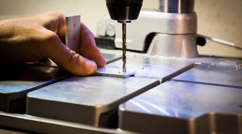
Holemaking in aluminium is often limited by chip evacuation rather than cutting power. Deep holes, blind holes and small diameters need a defined chip-control method. Polished drill flutes, through-tool coolant, peck cycles or chip-breaking drill geometry may be necessary, depending on the depth-to-diameter ratio. For reaming, leave a controlled and consistent stock allowance; too little stock can rub, while too much can overload the reamer and affect roundness.
Tapping needs attention because aluminium can gall on thread flanks. Form taps can produce strong threads in suitable ductile alloys, but they displace material and require the correct hole size. Cutting taps remove chips and may be preferred where chip evacuation is manageable or where material condition makes forming less predictable. In either case, lubrication is usually important for thread finish and tap life.
Feeds, speeds, coolant and chip control work as one system
Aluminium usually allows higher surface speeds than steel, especially with carbide tools, but the correct setting still depends on cutter diameter, coating, stickout, spindle power, machine stability and workholding. Tool manufacturer data remains the safest starting point because modern aluminium cutters can vary widely in recommended speed and feed. The operator should then tune the process by watching chip shape, spindle load, surface finish, burr formation, sound and tool wear.
A useful sequence is to set spindle speed within the tool’s recommended range, choose a realistic chip load, and then confirm that the machine can clear chips at the programmed material removal rate. Reducing feed to solve a poor finish can make the problem worse if it causes rubbing. The better correction may be a sharper tool, higher cutting speed within limits, improved coolant direction, more rigid fixturing or a toolpath that reduces chip packing.
| Observed problem | Likely cause | Common correction |
|---|---|---|
| Smeared or cloudy finish | Built-up edge, rubbing or poor lubrication | Use a sharper tool, increase chip load carefully, improve lubrication or replace a worn cutter |
| Chips welding to flutes | Insufficient evacuation or excessive heat at the edge | Add air blast, flood coolant, polished flutes or a toolpath with more chip clearance |
| Heavy burrs | Tool wear, wrong exit strategy or overly ductile condition | Adjust tool sharpness, edge break strategy, support at exit and finishing allowance |
| Chatter in pockets | Excessive stickout, thin walls or unstable engagement | Shorten tool, reduce radial load, add support or change toolpath entry and exit |
| Oversized or tapered holes | Drill walking, packed chips or thermal growth | Use spot drilling where appropriate, better coolant delivery, pilot strategy or reaming |
Coolant choice is not only about temperature. In aluminium machining, lubricity helps reduce adhesion and improve finish. Flood coolant is common on CNC mills and lathes, while air blast or minimum-quantity lubrication may be used where dry chip handling is preferred. The right choice depends on machine design, part geometry, chip volume, environmental controls and downstream cleaning needs. See also: CNC Machining.
Dimensional accuracy depends on fixturing and stress control
Aluminium parts can be easy to cut but difficult to hold. Thin plates, deep pockets, tall ribs and thin walls may deflect under clamping force or cutting pressure. When the clamp is released, the part can spring out of tolerance even though it measured correctly in the fixture. This is common in aerospace-style monolithic parts, lightweight brackets, electronics housings and covers with large pockets.
Good practice starts with supporting the part close to the cut and reducing unnecessary tool pressure. Soft jaws, vacuum fixtures, modular plates, sacrificial supports and adhesive or wax-based support methods can all be useful in the right context. The fixture should locate the part repeatably without crushing soft surfaces. If cosmetic faces matter, clamping marks and chip dents should be considered before the first operation begins.
Residual stress is another factor. Removing a large volume from one side of plate or extrusion can release stress and move the part. Roughing both sides, leaving rest time where schedules allow, using stress-relieved stock, and leaving a semi-finishing allowance can reduce surprises. For tight tolerances, it is often better to separate roughing, stress-relief strategy and final finishing than to try to hit final size in one aggressive pass.
Thermal management also matters. Aluminium conducts heat well, but local heating still changes dimensions during inspection and machining. A part measured immediately after heavy cutting may not match the same part after it returns to room temperature. Shops holding close tolerances should control part temperature, coolant temperature, inspection timing and deburring methods.
Safety and quality checks should not be treated as afterthoughts
Machining chips are usually less hazardous than fine dust, but aluminium dust from grinding, sanding or dry collection can create fire and explosion concerns. OSHA materials on combustible dust identify metal dusts, including aluminium, as potential hazards when particles become suspended at the right concentration. Shops should use appropriate dust collection, housekeeping, hot-work controls and material-specific procedures rather than assuming aluminium is harmless because it does not spark like steel in every operation.
Chip handling also deserves attention. Long stringy chips can cut hands, clog conveyors and wrap around rotating tools. Coolant-covered chips are slippery, and fine chips can pack into pockets, fixtures and toolholders. Good housekeeping protects both operators and part quality.
Final inspection should match the real function of the part. For a structural bracket, dimensional accuracy, flatness and hole location may dominate. For a sealing surface, surface roughness and burr control may be more important. For an anodised housing, tool marks, embedded chips and inconsistent grain direction can show through the finish. A useful aluminium machining checklist includes:
- Verify alloy and temper before programming final parameters.
- Use sharp, aluminium-appropriate tools with adequate flute polish and chip space.
- Confirm coolant or air delivery reaches the actual cutting zone.
- Check workholding for distortion before and after unclamping.
- Plan deburring so edges meet function without rounding critical geometry.
- Inspect temperature-sensitive dimensions after the part stabilises.
- Keep aluminium dust, chips and mixed-metal debris under controlled housekeeping procedures.
Frequently asked questions
Is aluminium machining easier than steel machining?
Aluminium usually requires less cutting force than steel and can often be machined at higher spindle speeds. It is not always easier. Soft alloys can smear, long chips can clog tools, and thin aluminium parts can distort during clamping or after roughing. The process is easier only when tooling, chip control and fixturing are matched to the material.
Which aluminium alloy is easiest to machine?
Free-machining alloys such as 2011 are commonly associated with excellent chip control, while 6061-T6 is widely used because it balances machinability, strength, availability and cost. The easiest grade for a specific job depends on required strength, corrosion resistance, finishing, regulatory constraints and availability, not just cutting speed.
Do aluminium parts need coolant?
Many aluminium operations benefit from coolant or lubrication because it reduces adhesion and helps prevent built-up edge. Some operations can run with air blast or minimum-quantity lubrication if chips are cleared reliably and the tool is designed for the method. The decision should be based on chip evacuation, finish, tool life, machine design and cleaning requirements.
What causes a poor finish when machining aluminium?
Common causes include a dull tool, built-up edge, too little chip load, poor coolant access, chip recutting, runout, chatter or unstable workholding. Before reducing feed, check whether the tool is actually cutting cleanly. A sharper cutter, better chip evacuation or improved toolpath may solve the finish problem more effectively.
How can burrs be reduced in aluminium machining?
Burr reduction starts with sharp tools, stable support, correct feed per tooth and controlled tool exit. Climb milling, optimized finishing passes, chamfer tools and planned edge-break operations can help. For thin or soft parts, fixture support near the edge is often just as important as cutter geometry.