
How to Measure Surface Roughness?
What Is Surface Roughness and Why Does It Matter in Engineering?
Surface roughness matters a lot in how materials act after you make them. In engineering, it’s not just about looks. It’s about how two surfaces work together when they touch. They might slide, seal, or hold weight. How you check and manage surface roughness sets the performance, life span, and even safety in many fields. Think about a car engine. If the parts are too rough, they wear out fast. That could lead to breakdowns on the road.

Definition and Concept of Surface Roughness
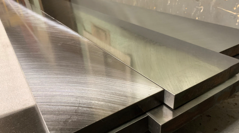
Surface roughness means the small bumps and dips on a material’s face from making it. These bumps are tiny, often too small to see without tools. But they change how the part works. It’s a main way to judge surface feel and quality. Roughness shows if a surface is smooth or bumpy. It affects how surfaces touch and move. For instance, a smooth face cuts down rubbing in wheels that turn. A bit bumpy one might keep oil in place better. In real jobs, like fixing bikes, a rough chain link can make pedaling harder.
The Role of Surface Roughness in Functional Performance
How well an engineered piece works ties closely to its face condition. Surface roughness changes rubbing, how much it wears, and how it holds grease. In exact work, it sets how well it seals and lasts under repeated stress. That’s key for plane parts or water systems. A failure there could cause big problems. Even light bounce, power flow, and paint sticking depend on it. Light reflection shifts with tiny texture. Power paths change too. Paint might not hold on bumpy spots. I’ve seen in workshops where a rough bolt head makes assembly tricky, adding extra time.
Common Parameters Used to Describe Surface Roughness
When engineers chat about surface roughness, they point to numbers like Ra, Rz, and Rt. Each one looks at the surface in a different way. Ra shows the average bump from the middle line. Rz checks the big ups and downs between high points and lows. Rt covers the full up-and-down range. You pick based on what the job needs and rules in the field. For plane parts, they often set Ra in narrow bounds to keep air flow smooth. In auto shops, a Ra of 0.8 micrometers might be the goal for piston rings to reduce oil use.
How Is Surface Roughness Quantified in Practice?
To measure surface roughness, you need exact tools and steady setups. You choose touch or no-touch ways based on the stuff, if it scratches easy, how fine you need it, and how quick the line runs.
Contact Profilometry Techniques
Contact profilometers have a small tip that runs over the face to note height changes. This way gives strong truth for flat, two-way surface checks. It measures push as the tip goes over highs and lows. But there are downsides. The press might scratch the face. It also takes more time than light tools. For tough metals or cut parts that last, this stays the usual pick. It repeats well. Picture checking a gear tooth. The tip traces it without missing spots.
Non-contact Optical Measurement Methods
No-touch light ways, like interferometry or confocal microscopy, use light bounce to map faces. They don’t touch at all. They grab clear three-way height maps fast by looking at light mix or bounce strength. These fit soft stuff like plastics or thin covers where touch could mess it up. They scan big spots quicker. And they keep tiny measure down to billionths of a meter in height. In labs, I’ve watched them map a phone screen in seconds, spotting dust specks.
Advanced Digital Metrology Systems
Today’s digital measure tools use laser sweeps and white light mixers for very fine detail, down to billionths. They link with computer programs for auto check of data. This cuts hand mistakes in review. Some top setups mix touch and light ways into one unit. They blend the best of each for full texture maps on tricky shapes. It’s like having a all-in-one scanner for engine blocks, catching both big waves and small pits.
Why Do Different Industries Require Specific Roughness Standards?
Each field sets its own okay level for surface finish. That’s because jobs differ a ton. From stopping leaks in water lines to light bounce in eye gear.
Manufacturing and Machining Applications
In cutting jobs, the tool speed, cut rate, and cooler fluid all shape the end face quality. Rules help so parts from varied shops fit right in build. Keeping roughness in bounds cuts wear on moving bits. It boosts fit exactness over make lines. For example, in a factory making tools, a standard Ra under 1.6 micrometers ensures drills last longer without jamming.
Aerospace and Automotive Engineering Requirements
Plane parts need tight roughness limits. Air flow over smooth spots like fan blades or body sheets sets how well it flies. Good finish cuts break risk under repeat pulls in air or motor runs. Following ISO or ASME rules keeps trust and safe use in hard spots. In cars, smooth cylinder walls, say Ra 0.4, help engines sip less fuel and run quieter.
Semiconductor and Optics Industries Needs
In chip or lens making, even tiny shifts count. Super smooth faces are a must for chip disks. Flat at atom size affects how circuits run. Lenses need exact rub down. Any small bump changes light bounce or picture sharp. Tools here spot under-micron shifts steady with high-detail light mix gear. A single scratch on a chip wafer can scrap a whole batch worth thousands.
What Are the Challenges in Measuring Surface Roughness Accurately?
Right measure isn’t just about tool sharpness. It’s also about steady air around, how you pick spots to check, and fair read of numbers.
Influence of Measurement Environment and Setup
Heat shifts make stuff grow or shrink. That twists reads at small scales. Shakes from close machines add junk to data. To fight this, you tune tools to known samples for steady truth over time. Good hold stops bends in scan work. In a busy plant, a quick temp jump from machine heat can throw off a reading by 10% if not watched.
Limitations of Measurement Resolution and Sampling Density
If you check too few spots, small flaws hide. If too many, data piles up with little gain. You balance quick work with true detail. That’s big in work spots where speed counts as much as sharp check. For a part like a valve, sampling every 0.5 mm might miss a 0.1 mm pit that causes leaks later.
Data Interpretation and Parameter Selection Issues
Picking wrong numbers can lead to bad calls on if it’s good enough. Varied tools give hard-to-match results if clean settings differ. Engineers read based on clear number meanings. This keeps checks the same over labs or make sites. Sometimes, teams argue over Rz vs. Ra, but sticking to one standard clears it up.
How Can Measurement Accuracy Be Improved Through Technology?
Tech keeps pushing measure work to auto runs, smart check, and mix setups. All to get sure reads quicker.
Integration of Automation in Metrology Systems
Auto scans cut people slips in repeat checks. They follow set paths exact each go. Robot holds boost repeat on hard shapes like fan blades or body implants. Linking data grab with make control gives live back talk. So cut settings shift auto when roughness goes off bound. In a line making phone cases, this spots a bad batch in minutes, saving waste.
Use of Artificial Intelligence in Data Analysis
Smart machines add speed to measure by handling big data fast. They spot odd bits old ways miss. Learn models guess best cut settings from past roughness paths. This helps fix jobs before flaws show. Smart clean cuts junk without dropping key bits for true review. It’s like having a brain that learns from every scan, getting sharper over time.
Development of Hybrid Measurement Approaches
Mixing touch trace with light scan widens what stuff you can check. From shiny metals to see-through covers in one flow. Mix setups give big-scale cover for large bits and small-scale sharp for fine parts at once. This full way backs deeper texture check over varied stuff in today’s makes. For coated tools, it layers data to show if the cover hides base flaws.
How Does Surface Roughness Relate to Material Properties?
Surface feel doesn’t stand alone. It grows from how stuff acts in cuts, shapes, covers, or heat works.
Correlation Between Material Hardness and Surface Finish
Tougher stuff often ends smoother under same cut jobs. It fights bend along tool lines better than soft kinds. Tool wear shifts with tough levels too. Picking right tool stuff gets key when aiming set Ra in end cuts. Softer aluminum might need slower speeds to match steel’s finish, or it gets wavy.
Impact of Coatings on Measured Roughness Values
Thin covers change seen roughness. Put-on ways like spray or plate add their own small builds on base faces. Uneven thick can twist light reads unless tuned first with match samples close to cover traits. In bike frames, a powder coat might smooth a rough weld, but measure it wrong and you think it’s flawless when it’s not.
Influence of Heat Treatment Processes on Surface Texture
Heat rounds change small builds through grain spread or shift turns that quietly remake height at small scales. Set heat can boost smooth by easing left stress after cuts. Or it makes wanted bump patterns for better stick of next covers. After quenching a blade, the surface might roughen slightly, needing a quick polish to meet specs.
What Future Trends Are Shaping Surface Roughness Measurement?
Measure keeps growing to hand-carry gear, better see tools, and same world rules. All to make sharp check easier everywhere.
Miniaturization of Metrology Instruments
Hand-held tools let workers do sharp checks right at the spot. No need to ship bits to far labs. Small sensors fit into make lines for steady watch. Wireless send lets far check of quality over spread sites. Imagine a field tech scanning a wind turbine blade on a hill, sending data back instantly.
Advancements in 3D Topography Visualization
Fresh see math makes real three-way builds. You can poke around measured faces from many sides. Workers zoom to flaws like under a glass but share fast over web spots for team chat world-wide. It’s handy for spotting why a part failed, like a hidden crack in a bridge joint.
Standardization Efforts for Global Compatibility
World groups push for same meanings of roughness numbers. So makers over lands use the same words for finishes. Same rules ease world chain fits. Clear terms boost talk among plan folks, sellers, checkers. It lifts product trust where it’s used. With global teams, one standard cuts mix-ups in shipping parts from Asia to Europe.
FAQ
Q1: What instrument measures surface roughness most accurately?
A: White light interferometers generally provide the highest accuracy because they achieve nanometer-level vertical resolution without touching the sample surface.
Q2: Why does Ra alone not describe full surface texture?
A: Ra averages deviations but ignores peak shape distribution; combining it with Rz or Rt gives a more complete profile description useful for functional analysis.
Q3: Can temperature affect measurement results?
A: Yes—temperature changes cause expansion that shifts reference points microscopically; stable environmental control is essential during precision metrology work.
Q4: What industries rely most heavily on ultra-smooth finishes?
A: Semiconductor fabrication and optics manufacturing demand atomic-level smoothness since even small irregularities disrupt electrical pathways or optical clarity.
Q5: How does automation benefit routine inspection?
A: Automated systems eliminate operator variability by repeating identical scan paths each cycle while feeding real-time data back into process control loops for adjustment before defects occur.