
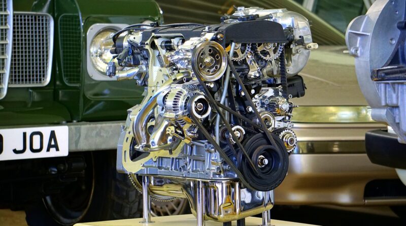
Is Prototype CNC Machining the Fastest Way to Test Real Metal Parts?
Why Does Prototype CNC Machining Still Matter Before Production?
Prototype CNC machining is still a safe first step when a printed concept or soft mockup cannot show how a real part will cut, fit, seal, or wear. If you are checking process options for a new bracket, housing, shaft, valve body, or fixture, the CNC Machining section can help you sort out material, tolerance, and finish before tooling cost is locked in.
A CNC prototype is not only a shape check. It is a small trial run. You can see burrs, tool marks, wall movement, thread quality, and assembly gaps in the same material planned for end use. That feedback is hard to get from a display model.
Real Material Before Tooling
CNC machining starts with bar, plate, or billet stock, then cuts away material to make the part. The idea is simple, but it matters in testing. Aluminum 6061, 7075, stainless steel 304, POM, PEEK, and brass do not react the same way under load, heat, coolant, and clamping. A machined aluminum prototype can show thread pull-out risk, edge strength, and surface wear much better than a resin model.
One Part Can Still Need Production Thinking
A single prototype can still hide production problems if it is treated like a one-off craft job. It is better to machine it with repeatable setups, normal cutters, and inspection notes that can carry over to low-volume production. Even for one sample, ask which faces should be datums, which holes locate the assembly, and which surfaces are only for appearance. Those choices keep the first sample closer to the later production part.
Drawing Quality Drives Quote Quality
A STEP file shows the shape, but a drawing tells the shop what matters. Without a drawing, the machinist may treat all features as equally critical. That can raise the price, or worse, miss the one bore that controls the function. A clear 2D drawing with tolerances, thread callouts, finish notes, and material grade reduces back-and-forth. It is not fancy work, but it saves real time.
When Should You Choose CNC over 3D Printing?
3D printing is useful, especially for complex shapes and quick visual checks. CNC often makes more sense when the prototype has to work like the final part. NIST public additive manufacturing material, accessed in July 2026, describes additive processes as building parts layer by layer from a digital file. That layer-by-layer method has its place, but it is not the same as cutting a part from wrought metal or engineering plastic stock.
Metals, Plastics, and Real Surface Behavior
If your test depends on real material strength, sealing, sliding, wear, or torque, CNC is usually the lower-risk choice. A machined stainless part can go into a corrosion or wear trial. A machined POM slider can run against a mating rail, and a machined aluminum heat sink can be tested with real contact surfaces. Printed parts may still help in the early stage, but the result may not carry over cleanly.
Tight Features and Post-Machining Control
CNC is useful for flat faces, bores, tapped holes, slots, bearing seats, and datum-controlled assemblies. It also supports post-machining work such as deburring, bead blasting, anodizing, passivation, or polishing. If a prototype needs an O-ring groove with a controlled surface or a shaft bore that lines up with another feature, machining gives the supplier more direct control. That control can make the test result easier to trust.
Hybrid Prototypes for Complex Shapes
Sometimes the right answer is not CNC vs printing. It is both. A printed casting-style body can check packaging, while CNC inserts handle threads, bearing bores, or sealing faces. For early medical, robotics, electronics, and automotive projects, this mixed method can reduce cost while keeping the test areas useful.
How Can You Design a Prototype That Machines Cleanly?
A good CNC prototype starts before the quote. Small design choices decide whether the job runs smoothly or spends hours on special tools. Public design guidance from Hubs, accessed in July 2026, notes that cavities and holes down to 2.5 mm can be CNC machined with standard cutting tools. That does not mean every small feature is cheap. It means the designer should know where standard tooling stops and special work begins.
Wall Thickness That Survives Clamping
Thin walls can look fine in CAD, then move during machining. Metals may spring after roughing, and plastics may flex under clamping or heat. If a wall does not need to be very thin for function, make it thicker. For many prototype housings, adding 0.5 mm to 1 mm in non-critical areas makes the part easier to hold and less likely to chatter.
Hole, Thread, and Pocket Choices
Deep blind holes, tiny tapped holes, and square inside corners slow the job. Use common thread sizes where possible. Keep blind threaded holes deep enough for engagement, but not so deep that tapping becomes risky. For pockets, avoid deep narrow slots unless the function really needs them. A cutter needs room to enter, move chips out, and leave a workable corner radius.
Radius Choices That Save Cycle Time
Internal sharp corners are a common prototype problem. A round cutter naturally leaves a radius. If the drawing calls for a sharp inside corner, the shop may need EDM, broaching, hand fitting, or a design change. A larger inside radius lets a stronger cutter run faster. In a small pocket, changing a 0.5 mm radius to 2 mm can turn a slow, careful cut into a normal operation.
- Use larger internal radii when the mating part allows it.
- Mark only functional sharp edges as critical.
- Break non-critical edges to reduce handling risk and burr complaints.
Which Tolerances Matter Most on a First Prototype?
Tolerances are often where prototype cost jumps. A tight tolerance is not wrong, but a tight tolerance on every face is rarely needed. ISO 2768-1:1989 covers general tolerances for linear and angular dimensions without individual tolerance notes. ASME Y14.5-2018 gives rules and symbols for GD&T, the language many U.S. drawings use to define functional geometry. These references do not decide your product needs, but they give buyers and shops a shared way to read the drawing.
ISO 2768 for Non-Critical Dimensions
For simple prototype parts, ISO 2768 can work well as a default note for non-critical features. It keeps the drawing readable and avoids calling out every small length. Use general tolerances for clearance edges, cover outlines, and non-mating faces. Then call out tighter values only where fit, motion, sealing, or safety depends on them.
ASME Y14.5 for Functional Features
GD&T helps when position, flatness, perpendicularity, runout, or profile matters more than a basic plus-minus size. A bolt pattern that locates a motor, for example, may need true position from datums. A sealing face may need flatness, and a bearing bore may need size, roundness, and relation to another bore. Clear datums also make inspection less open to personal judgment.
Tolerance Stackups Before Cosmetic Details
Before spending budget on a perfect exterior, check the stackup. Which features control assembly? Which gaps can float? Which dimensions add together across several parts? Protolabs machining guidance, accessed in July 2026, lists a standard prototype and production machining tolerance of plus or minus 0.005 inch for many machined parts. That public number is a useful reference, but it is not a promise for every geometry, material, or supplier. Thin walls, large parts, deep bores, and plastics may need wider limits. See also: CNC Programming.
How Do Materials Change Cost, Lead Time, and Risk?
Material choice can change cutter wear, surface finish, burrs, warpage, inspection method, and even packaging. There is no reliable public data source that gives one universal lead time for all prototype CNC machining jobs, because shops differ by machine capacity, region, material stock, and inspection load. A simple aluminum plate may ship fast. A stainless manifold with deep holes and tight sealing faces will not run the same way.
Aluminum for Fast Iteration
Aluminum 6061 is common because it machines well, takes anodizing, and fits many brackets, housings, fixtures, and test parts. Aluminum 7075 gives higher strength, but it can cost more and may need more review for stress, corrosion environment, and finish choice. If you need three design loops in a month, aluminum often helps keep the project moving. It is also easy for most CNC suppliers to source.
Stainless Steel for Wear and Corrosion Tests
Stainless steel is a better choice when the prototype must face corrosion, cleaning chemicals, food contact conditions, or higher wear. It cuts slower than aluminum and can work harden if the process is not controlled. Expect more machining time and more attention to burrs. For valve bodies, shafts, pump parts, and lab hardware, the extra cost may be justified because the test is closer to real service.
Engineering Plastics Need Extra Care
Engineering plastics such as POM, PTFE, nylon, and PEEK can work well for low friction, insulation, weight reduction, or chemical resistance. They also move more with heat and clamping. A plastic prototype may measure fine right after machining, then shift after stress relaxes. If the part has thin walls or tight flatness, tell the supplier how it will be used and inspected.
What Should You Send to a CNC Supplier Before Quoting?
A good quote package is boring in the best way. It answers common questions before they turn into emails. The supplier can price the work based on real requirements, not guesswork. If you need a serious prototype, send more than a model and a message that says, quote this please. That short line has probably made plenty of machine shops sigh on a Monday morning.
A Clean STEP File and 2D Drawing
Send a STEP file for geometry and a PDF drawing for requirements. The model should match the drawing revision. Remove unused bodies, hidden concept geometry, and old hole patterns. On the drawing, show material, finish, units, scale, revision, and general tolerance. If only a few dimensions matter, make that clear so the shop does not quote every surface as critical.
Critical Surfaces, Datums, and Inspection Notes
Mark the surfaces that must be protected. Add datums for functional checks. If the prototype needs inspection data, say which dimensions need a report. Do not ask for a full inspection report if only three features matter. A focused report is easier to review and often costs less to produce.
Quantity, Finish, and Use Case
Quantity changes setup planning. One part, five parts, and fifty parts may use different holding methods. Finish also matters. A raw machined prototype is not the same as bead blasted, anodized, passivated, or polished. Tell the supplier what the part does. A short note such as holds a sensor during vibration test or seals against a silicone gasket can prevent wrong assumptions.
- Send STEP and PDF files with the same revision.
- Separate must-have tolerances from nice-to-have dimensions.
- List material grade, quantity, surface finish, and inspection needs.
- Share the mating part or assembly context when fit is critical.
FAQ
Q1: What Is Prototype CNC Machining? A: Prototype CNC machining is the use of computer-controlled milling, turning, drilling, or related cutting processes to make early test parts from real metal or plastic stock before full production.
Q2: Is CNC Better Than 3D Printing for Prototypes? A: CNC is usually better when you need real material behavior, tight bores, threads, sealing faces, wear testing, or production-like surface finish. 3D printing is often better for quick shape checks and very complex internal forms.
Q3: What Tolerance Should You Use for a CNC Prototype? A: Use general tolerances for non-critical features and tighter callouts only for functional areas. ISO 2768 and ASME Y14.5 are common references, but the right tolerance depends on material, geometry, size, and how the part works.
Q4: Which Material Is Best for a First CNC Prototype? A: Aluminum 6061 is a common first choice for fast mechanical prototypes. Stainless steel, brass, POM, PEEK, or other materials make sense when the test needs strength, corrosion resistance, sliding behavior, heat resistance, or electrical insulation.
Q5: How Can You Reduce CNC Prototype Cost Without Hurting Function? A: Use common material, avoid very deep pockets, allow larger internal radii, limit tight tolerances to critical features, and send a clear drawing. Small design changes can remove special tools and reduce machining time.