
What Are Machining Chips and How Can You Control Them Better?
What Are Machining Chips and Why Should a Shop Care?
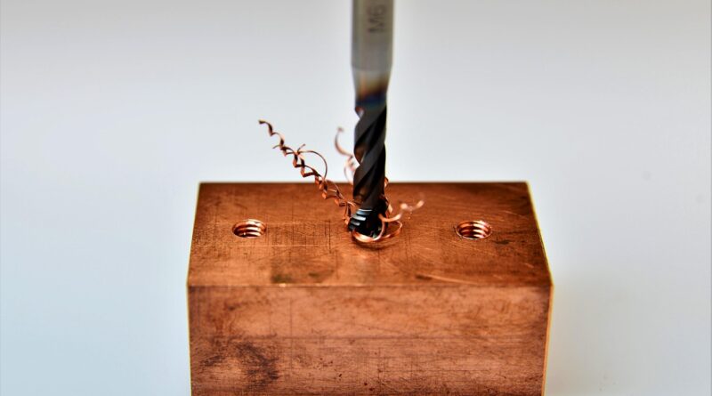
Machining chips are the small pieces of material removed during turning, milling, drilling, boring, sawing, and other subtractive work. They may look like waste in the chip pan, on the floor, or on a conveyor, but they give useful clues about the cut. If you run CNC or manual equipment, chips can show whether the tool is cutting cleanly, rubbing, getting too hot, or struggling with the material. For more background on how different cuts create different results, see the machining processes section.
A chip is more than a leftover curl of metal. It is the result of shear, heat, friction, tool geometry, coolant action, and machine rigidity. A neat chip does not prove the part is good, but a bad chip often gives an early warning. Long stringy chips wrap around tools. Powdery cast iron chips spread through the machine. Blue steel chips may point to high heat. Anyone who has cleaned a chip pan after a long shift knows this matters in daily work.
Chips Are Process Feedback
Chips show how the material separates from the workpiece. A steady chip flow usually means the cut is stable, while a sudden change in chip color, size, or sound can point to tool wear, chatter, or poor chip evacuation. NIST machining research has treated chip formation as a result of cutting speed, rake angle, and depth of cut, not as random shop debris. That is a useful shop view because the chip is part of the process data, even if it ends up in a scrap bin.
Chips Affect Safety and Part Quality
Long chips can scratch finished surfaces, jam conveyors, whip around rotating parts, and hide sharp edges under coolant. Short chips are often easier to move, but dust-like or needle-like chips can still cause cleanup and exposure problems. OSHA machine guarding guidance, checked in July 2026, lists flying chips and sparks among the hazards guards are meant to block. In plain terms, chip shape affects the part and the person standing near the machine. A chip problem is not only a housekeeping issue.
Chips Carry Material and Fluid Value
Metal chips still contain usable metal, and wet chips often carry cutting oil or water-based fluid. EPA recycling guidance treats metal pieces generated from machining as scrap metal when they are recycled for metal recovery. USGS Mineral Commodity Summaries 2026 reported U.S. apparent consumption of iron and steel scrap at about 57 million tons in 2025 and said the U.S. iron and steel scrap recycling rate averaged roughly 80% to 90% during the past decade. Sorted chips may not look important, but they belong to that larger recycling stream. Good sorting also saves arguments when scrap pickup comes around.
Which Machining Chip Types Tell the Most Useful Story?
Chip type depends on material, tool edge, cutting data, coolant, and rigidity. You do not need a lab to read the basic signs. Look at whether the chip is continuous, segmented, powdery, tightly curled, bird-nested, or welded to the edge. Then compare that chip with part finish, spindle load, tool wear, and machine sound.
Continuous Chips Signal Smooth Shearing
Continuous chips are common in ductile materials such as low-carbon steel, aluminum, and some stainless steels when the cut is running well. Seco Tools chip formation guidance notes that continuous chips often form with small chip thickness, high cutting speed, a sharp edge, a large rake angle, a smooth tool face, and good lubrication. That is fine in a catalog example. On a real lathe, the same continuous chip can turn into a long ribbon if it does not break, and that ribbon can become a safety problem fast.
Segmented Chips Point to Heat and Strain
Segmented chips, also called serrated chips, often show up in harder alloys, stainless steels, titanium alloys, and superalloys. They can show zones where the material is shearing hard, then letting go. NIST work on high-speed machining has linked discontinuous chip formation with higher tool wear, weaker surface finish, and reduced accuracy in some cutting conditions. This does not mean every segmented chip is bad. It does mean the operator should keep a close eye on heat, tool wear, and edge strength.
Built-Up Edge Chips Warn of Adhesion
Built-up edge happens when workpiece material sticks to the cutting edge and changes the cutting geometry. Seco Tools describes this as a common issue with soft and ductile materials, where the built-up material can break away and roughen the machined surface. On the shop floor, the tool starts cutting with a lump on its nose. Surface finish gets rough, size may move, and the operator may blame the insert before checking speed, coolant, coating, and rake.
How Do Speed Feed and Tool Geometry Shape Machining Chips?
Chip control is seldom fixed by one number. Speed, feed, depth of cut, edge prep, rake angle, nose radius, chipbreaker form, coolant direction, and workholding all play a part. Change too many things at once and the real cause gets lost. Change one thing at a time, then the chip usually tells you what changed.
Feed and Depth Set Chip Thickness
Feed and depth of cut set how much material the edge must shear. A very light cut may miss the chipbreaker and make stringy chips. A heavier cut may break chips better, but it also raises cutting force and heat. In boring, for example, short chips often help evacuation. Push the feed too far in a long bar, though, and chatter may start before the chip looks right. That is the kind of shop tradeoff no chart can fully solve.
Rake Angle Changes Cutting Pressure
A positive rake angle can lower cutting pressure and help the tool cut more freely, especially in aluminum and softer steels. A stronger negative or honed edge can take interrupted cuts and roughing loads better. The tradeoff is higher force. If the setup is not rigid enough, that extra force can turn into chatter, poor finish, or an insert edge that chips early.
Chipbreakers Need the Right Window
Chipbreakers work only inside a practical feed and depth range. Sandvik Coromant turning geometry training published in 2026 explains that finishing, medium, and roughing geometries are made for different feed and depth ranges. Put a finishing insert into a heavy roughing cut and edge damage can come quickly. Use a roughing insert in a light finishing pass and it may rub instead of cutting cleanly.
Why Do Machining Chips Hurt Safety Housekeeping and Coolant Life?
Chip control is not only about cycle time. It affects guarding, eye protection, coolant cleanliness, slip risk, waste handling, and machine uptime. A shop with poor chip handling loses time on cleaning, pump screens, stuck conveyors, scratched parts, and small injuries that should have been avoided.
Flying Chips Need Guarding
Flying chips are sharp, hot, and hard to predict. OSHA machine guarding guidance says machines that expose employees to injury must be guarded, and eye and face protection is required where flying particles create hazards. The safety point is simple, and the listed hazard is clear. Chip flight should not be treated as a normal nuisance just because it happens often.
Coolant-Wet Chips Need Control
Wet chips carry fluid out of the machine and into bins, carts, gloves, and floors. NIOSH Publication No. 98-102, issued in 1998 and still widely cited, recommends limiting metalworking fluid aerosol exposure to 0.4 mg per cubic meter for thoracic particulate mass, or 0.5 mg per cubic meter for total particulate mass, as a time-weighted average for up to 10 hours per day during a 40-hour week. Chips are not the only source of exposure. Still, wet chip handling is part of coolant control, especially when bins sit close to people or forklifts move them through the shop.
Chip Bins Should Stay Sorted
Mixed chips lose value and make recycling harder. Aluminum, stainless steel, brass, cast iron, and alloy steel should not land in the same tote unless the recycler accepts that mix. Keep tramp material out as well. Broken inserts, rags, gloves, and bolts do not belong in clean chip scrap. It sounds basic, but this is where basic habits pay. A clean labeled bin is cheaper than dealing with rejected scrap later. See also: CNC Machining.
How Can You Read Chips During Turning Milling and Drilling?
Each operation makes chips in its own way. Turning creates a more continuous chip stream. Milling cuts in and out with every tooth. Drilling pushes chips through flutes, often in a blind hole with little space. Reading chips means judging them in the context of the operation, not against one textbook photo.
Turning Chips Reveal Insert Load
In turning, chip color, curl radius, and break pattern can show insert load. Long ribbons may mean the chipbreaker is not being used in its proper range. Tight comma-shaped chips often point to better breakage, although very hard, tiny chips can still damage the edge. If the chip suddenly gets darker at the same feed and speed, check insert wear, coolant aim, and whether the workpiece skin is harder than expected.
Milling Chips Show Entry and Exit Problems
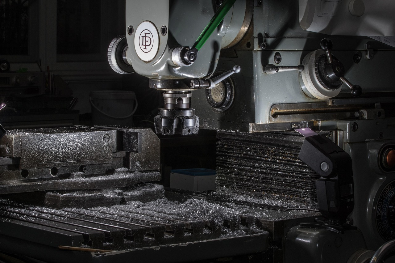
Milling chips change with cutter path. A chip that starts thick and exits thin behaves differently from one that starts thin and exits thick. Recut chips can weld to the edge and mark the surface, especially in aluminum. If chips pile up in a pocket, the next pass may cut the chip instead of the workpiece. That dull crunching sound is not something to ignore.
Drilling Chips Expose Evacuation Limits
Drilling needs room for chips to move up the flutes. Long spiral chips can pack inside the hole, raise torque, and break the drill. Short, steady chips usually leave the hole more easily. Pecking, through-tool coolant, sharper geometry, and the right point style can help. The material still matters, though. Some stainless grades make chip control difficult even with decent tooling.
What Practical Steps Improve Chip Control?
Better chip control starts with watching the cut, then making small changes. Good shops do not chase chip shape just for looks. They connect chip shape with tool life, surface finish, spindle load, coolant carryout, and worker safety. A clean blue chip still fails the test if it scratches the part or wraps around the chuck.
Start With a Safe Baseline
Set guarding, eye protection, and coolant containment before pushing cutting data. Use the tool maker’s starting range for the insert geometry, then compare the chip with the part. If chips are long, do not reach in with pliers while the spindle is running. Stop the machine first. It costs a few seconds. A hand injury costs far more.
Change One Cutting Variable at a Time
Pick one variable, record the result, and keep the change if it works. A simple test plan may look like this:
- Increase feed slightly to engage the chipbreaker if the cut is too light.
- Lower speed if heat, built-up edge, or welding gets worse.
- Change to a sharper or more positive geometry for gummy aluminum.
- Use a stronger edge for interrupted roughing or scaled stock.
- Aim coolant at the tool-chip contact point, not just at the general area.
This is not fancy work. It is repeatable, and repeatable beats guessing when the same job comes back next month.
Match Disposal to Material and Fluid
Drain wet chips before scrap pickup where your local rules and recycler allow it. Keep oil-bearing chips under cover, label bins by alloy family, and keep coolant runoff out of storm drains. EPA hazardous waste recycling guidance, checked in 2026, notes that scrap metal recycled for metal recovery is treated differently from many waste streams, but fluids and contaminants still need proper handling. If local rules are stricter, follow the stricter requirement and keep a record of the process.
FAQ
Q1: What Are Machining Chips? A: Machining chips are pieces of material removed by a cutting tool during operations such as turning, milling, drilling, boring, and sawing. Their shape and color can show how the cut is behaving.
Q2: Are Long Machining Chips Bad? A: Long chips can come from a smooth cut, but they can also wrap around tools, scratch parts, block conveyors, and create safety risks. They need control, especially on lathes.
Q3: Why Do Chips Turn Blue or Purple? A: Blue or purple chips often show high heat in steel cutting. That may be normal in some roughing work, but a sudden color change can also point to tool wear, poor coolant aim, or a speed problem.
Q4: Can Machining Chips Be Recycled? A: Yes. Clean, sorted metal chips are commonly recycled as scrap. Keep alloys separate, reduce coolant carryout, and follow recycler and local environmental rules.
Q5: What Is the Fastest Way to Improve Chip Control? A: Start with the right insert geometry for the operation, then adjust feed, depth of cut, speed, and coolant aim one step at a time. Watch the chip, the part finish, and tool wear together.