
What To Do When CNC Drilling Causes Tool Breakage And How To Prevent It
What To Do When CNC Drilling Causes Tool Breakage
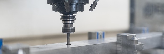
Tool breakage in CNC drilling is more than a nuisance—it’s a costly interruption that can compromise part accuracy, extend downtime, and damage the spindle assembly. The root causes often trace back to mechanical stress, tool geometry mismatch, or poor machine setup. Identifying early signs and responding with data-driven adjustments can save hours of rework. The key is not just reacting to breakage but creating a stable drilling environment through precise feed control, regular calibration, and predictive monitoring.
Understanding the Causes of Tool Breakage in CNC Drilling
In high-precision CNC drilling, tool failure rarely happens without warning. It often results from a combination of mechanical overload, incorrect cutting geometry, or subtle setup misalignments that accumulate over time.
Mechanical Stress and Improper Feed Rates
Excessive feed rates increase axial load and torque on the drill bit. When the feed per revolution exceeds the tool’s design limit, microfractures form along the cutting edge. These fractures grow rapidly under cyclic loading, leading to catastrophic failure. Incorrect chip load distribution also causes uneven cutting pressure across flutes, resulting in chatter and vibration that amplify stress concentrations. Balancing spindle speed and feed per revolution is therefore crucial for maintaining consistent chip thickness and extending tool life. For instance, when drilling hardened steel at 60 HRC, reducing feed by 10% can double tool longevity without sacrificing productivity.
Tool Geometry and Material Compatibility
Tool geometry directly influences how forces distribute along the drill’s axis. Using an inappropriate point angle or helix design disrupts chip evacuation efficiency—especially in ductile materials like aluminum where chips tend to stick to flutes. Material compatibility matters as well; pairing carbide tools with titanium alloys requires coatings such as TiAlN to resist heat softening. Using uncoated tools in such conditions accelerates flank wear due to elevated temperatures exceeding 800°C at the cutting zone. Selecting geometry that matches both workpiece hardness and chip behavior ensures smoother operation and lower wear rates.
Machine Condition and Setup Accuracy
Even perfectly chosen tools fail when machine alignment drifts. Spindle runout introduces lateral forces that distort hole geometry and fatigue the drill shank. Similarly, improper clamping or fixture vibration amplifies stress concentration near the drill tip. Regular calibration of machine axes prevents cumulative positioning errors that otherwise cause off-center entry points or uneven load distribution. A simple dial test indicator check before each shift can reveal microns of deviation that would otherwise go unnoticed until a tool breaks mid-cycle.
Identifying Early Warning Signs of Tool Failure
Before a drill breaks, it often “speaks” through sound, vibration, or thermal discoloration. Recognizing these indicators allows operators to intervene early.
Visual and Acoustic Indicators During Operation
A sudden change in cutting tone—often sharper or squealing—signals increased friction or chipping along one flute. Discoloration near the cutting edge indicates excessive heat buildup due to poor coolant flow or dull edges. Vibration marks on hole walls suggest imbalance or chatter initiation caused by worn bearings or unstable fixturing. Experienced operators often rely on auditory cues more than sensors because sound changes precede measurable torque spikes by several seconds.
Monitoring Tool Load Through CNC Parameters
Modern CNC controllers log spindle load in real time. Sudden spikes in torque readings usually reflect impending breakage as resistance rises sharply before fracture occurs. Real-time monitoring systems can detect abnormal cutting forces early enough for automatic feed reduction through adaptive control functions embedded in advanced CNC software. Integrating these systems transforms reactive maintenance into predictive stability management.
Corrective Actions After a Tool Breakage Event
When a drill snaps mid-operation, immediate containment prevents collateral damage to both machine and workpiece.
Immediate Steps to Minimize Damage
The first action is stopping spindle rotation instantly to avoid secondary scoring inside the bore. Next, inspect for embedded fragments before restarting any cycle; leftover pieces can jam subsequent drills or alter bore alignment. Cleaning coolant lines after breakage removes residual chips that might block flow during re-drilling operations.
Assessing Root Causes Through Process Data Analysis
After stabilizing production, analyzing process logs reveals why failure occurred. Reviewing recent changes in parameters—such as increased feed rate or new material batches—often identifies triggers quickly. Examining spindle load graphs alongside vibration data helps correlate anomalies with specific machining moments. Comparing programmed versus actual feeds also exposes operator deviations from standard procedures.
Preventive Measures for Avoiding Future Breakage
Avoiding repeat failures requires parameter refinement and better thermal management rather than mere replacement of broken tools.
Optimizing Cutting Parameters for Stability
CNC drilling stability depends on maintaining equilibrium between speed, feed, and temperature rise within acceptable thresholds.
Feed Rate Adjustment Strategies
Start with manufacturer-recommended chip load charts as baseline values for each material type. When drilling deep holes beyond 5×D depth ratio or hard alloys above 45 HRC, reduce feed incrementally by 5–15%. This approach maintains chip evacuation without overloading flutes while preventing built-up edge formation.
Speed Control Techniques
Maintaining consistent surface speed across varying diameters through constant surface speed (CSS) mode keeps cutting conditions uniform along hole depth. Avoid abrupt acceleration profiles during retracts since transient loads can snap small-diameter drills under torsional stress.
Enhancing Cooling and Chip Evacuation Efficiency
Thermal regulation plays an equal role as mechanical balance in preventing fracture propagation along carbide grains.
Coolant Flow Optimization
High-pressure coolant delivery directly into the cutting zone is essential during deep-hole operations exceeding 10×D depth ratios. Through-spindle coolant systems enhance chip removal efficiency while stabilizing temperature gradients between core and edge zones.
Chip Management Practices
Program periodic peck cycles every few millimeters of depth to break long chips effectively and prevent clogging within flutes. For ductile materials such as copper alloys or aluminum, applying specialized chip-breaking geometries improves surface finish while reducing re-cutting risk.
Advanced Troubleshooting Techniques for CNC Drilling Stability
As machining centers evolve toward smarter ecosystems, data-driven troubleshooting becomes indispensable for maintaining uptime.
Utilizing Tool Condition Monitoring Systems (TCMS)
Integrating sensors capable of tracking vibration amplitude, acoustic emission levels, and temperature rise during drilling cycles provides real-time insight into tool health status. Predictive algorithms within TCMS platforms estimate remaining tool life based on accumulated wear signatures rather than arbitrary cycle counts—a leap forward from traditional time-based replacement schedules.
Leveraging Simulation Software for Process Optimization
Before mass production begins, simulating drilling dynamics under multiple parameter combinations helps identify stable operating zones free from resonance peaks or thermal distortion risks. Digital twin models replicate physical machines virtually to evaluate how thermal deformation affects alignment accuracy over extended runs—a valuable capability when tolerance windows shrink below ±0.01 mm.
Integrating Preventive Maintenance into Daily Operations
Preventive maintenance forms the foundation of sustainable precision manufacturing where consistency outweighs speed alone.
Scheduled Machine Inspections and Calibration Routines
Routine verification of spindle bearings’ condition, collet concentricity checks using precision gauges, and turret alignment audits should be embedded into weekly maintenance schedules. Replacing worn drawbars or hydraulic clamps restores rigidity lost over months of high-cycle operation—a small investment compared with recurring tool losses from instability.
Operator Training and Data Feedback Loops
Skilled setters interpret sensor feedback intuitively during setup trials; training them to adjust feeds proactively based on live data closes the loop between programming intent and actual performance outcomes. Establishing continuous communication among operators, programmers, and maintenance teams fosters iterative improvement across all aspects of CNC drilling reliability rather than isolated fixes after failures occur.
FAQ
Q1: What are the most common reasons drills break during CNC operations?
A: The main causes include excessive feed rates creating axial overloads, misaligned spindles producing lateral stress, poor cooling leading to heat cracks, and mismatched tool geometry causing uneven chip evacuation.
Q2: How can operators detect early signs of tool fatigue?
A: Changes in cutting noise pitch, visible discoloration near edges, rising spindle load readings, or irregular hole finishes usually indicate progressive wear before complete failure occurs.
Q3: What should be done immediately after a drill breaks?
A: Stop rotation instantly, remove fragments safely from the bore area, clean coolant passages thoroughly, then review recent process logs before resuming machining activities.
Q4: How does adaptive control help prevent future breakages?
A: Adaptive control automatically adjusts feed rates when it senses overload conditions via torque feedback loops inside modern CNC systems—reducing human reaction delay significantly.
Q5: Why is regular calibration critical even when no issues appear?
A: Minor misalignments accumulate gradually; regular calibration ensures positional accuracy stays within microns so stress remains evenly distributed across all axes during high-speed drilling cycles.