

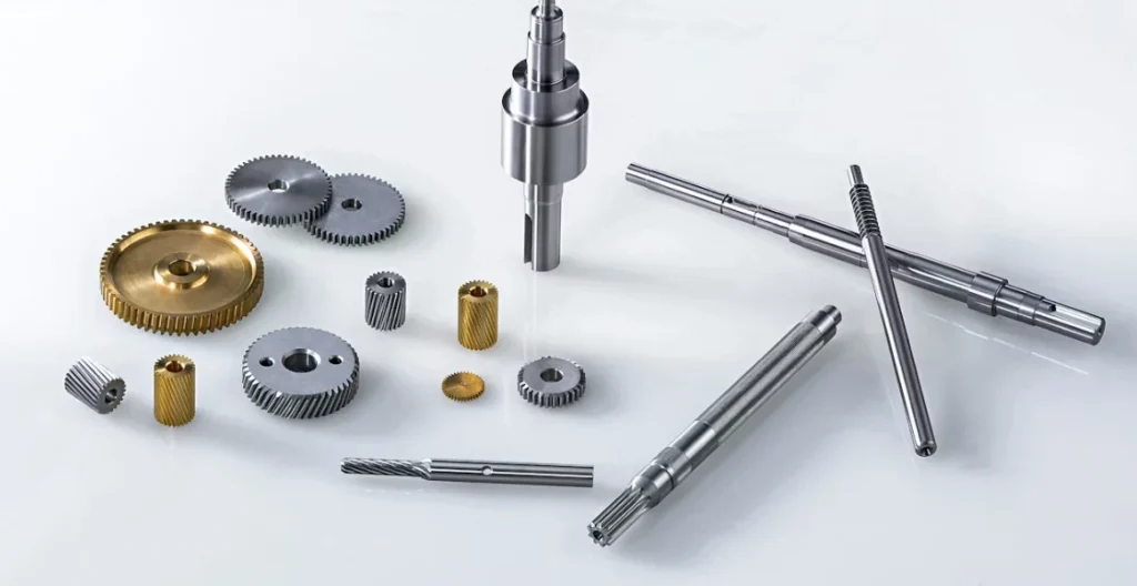
How Does Insert Selection For Turning Influence Chip Breaker Efficiency
The Secret to Matching Chip Breakers to Your Feed Rate
In turning operations, chip control is one of those things that quietly decides if your process goes well or becomes a big hassle for upkeep. Picking the proper insert and chip breaker mix has a big effect on surface finish, tool life, and even how much time your machine stays up and running. When you consider insert choice for turning, the form of both the insert and its chip breaker setup needs to match your feed rate and cutting setup. Let us examine how these elements work together. We can also see what actions you might take to achieve steady outcomes from your tool arrangement.
The Relationship Between Insert Selection and Chip Breaker Efficiency
Chip breakers are not simply cuts on an insert. They are planned parts that steer how chips shape up, bend, and clear out during the cut. If you have spotted long, messy chips twisting around a piece, that usually signals weak chip handling. It is not often due to poor material or speed picks. Good chip splitting holds heat back from the cutting edge. It also lessens rubbing on the rake face.
The Function of Chip Breakers in Turning Operations
Chip breakers handle three basic tasks. They manage chip shaping. They steer chip movement. And they assist in clearing chips from the cutting area. Well-planned breakers boost surface finish. They keep chips from scraping the workpiece. They also aid in making tools last longer. This happens because shorter chips move heat away in a better way. However, if chips do not split correctly, they can build up close to the cutting edge. This boosts temperatures. It speeds up wear. In busy production setups, like those for automotive shaft turning, this poor work can soon lead to lost time. Take a typical factory line where chips clogged the setup during a rush job on steel rods. The team spent an extra hour cleaning up, which delayed the next batch by 30 minutes.
How Insert Geometry Affects Chip Flow
Insert geometry sets how chips act after they move past the cutting edge. Things like rake angle, land width, and groove depth decide how much a chip bends before it snaps. Positive geometries often fit light or finishing cuts. They cut down on cutting forces. And they create slimmer chips. Negative geometries work better for roughing dense materials. In those cases, lasting strength counts more than a keen edge. The nose radius has a quiet yet key part. Larger radii make chunkier chips. These can fight against breaking at slow feeds. Smaller ones push for regular splitting. In a real-world example from a bike part maker, switching to a smaller nose radius on aluminum turned messy chips into neat curls, saving time on cleanup.
Factors Influencing Insert Selection for Turning
Choosing inserts for turning is not just about form or scale. It involves pairing the basic traits of both the tool and the workpiece with what you expect in the conditions. You must think about hardness, break resistance, and heat handling when picking which grade or coating suits best.
Material Properties of the Workpiece
Various materials call for distinct insert features. Tough alloys like Inconel call for inserts with solid edge power and strong heat resistance. Flexible steels gain from steady chip movement to dodge built-up edge buildup. Fragile materials like cast iron do better with inserts that reduce shock stress at the start. This frequently comes from negative rake angles teamed with firm breaker plans. For instance, in a foundry working on engine blocks, using negative rake inserts cut down on entry cracks by about 40 percent compared to sharper ones.
Cutting Conditions and Their Impact on Insert Performance
Cutting settings, such as feed rate, speed, and depth of cut, have a direct hand in how chips shape and split. High feed rates produce fat chips. These require bold breaker forms with deep slots for sure bending. On the flip side, at low feeds in finishing runs, keener edges are vital to hold clean splitting without too much sliding. Tweaking these settings without shifting insert geometry can result in odd chip forms. It may even bring early tool breakdown. Imagine a workshop pushing speeds on titanium without new inserts. The chips bunched up, and tools failed after half the expected life, costing extra replacements.
Matching Chip Breaker Design to Feed Rate Parameters
Feed rate might be the most touchy factor in turning. It shifts chip thickness quicker than any other setting. Each feed level ties to a particular kind of chip breaker form. This form aims for steadiness and good work.
The Role of Feed Rate in Chip Formation Dynamics
As feed rises, chip thickness grows in line with it. This changes the bend during shaping. At fair feeds, chips bend easily into C-like twists. At quicker feeds, they turn bulkier and tougher to deal with. This holds true unless you use deep-slot plans to back them. Going too speedy can burden an insert’s edge power. It leads to nicks or bad surface finish from shake-caused unsteadiness. In one machining class I attended, they showed how a 20 percent feed jump without breaker changes caused vibrations that marked a test bar all over.
Selecting the Right Chip Breaker for Different Feed Ranges
Low Feed Applications
When you work at low feeds, like 0.05 mm/rev or under, the tough part is dodging long, chewy chips that stick to the piece or holder. Tight-spaced breakers or small-groove setups help start bending soon, even with slim chips. You find these plans in careful finishing of stainless steel shafts. In those jobs, even results count more than quick material take-off. A precision shop once used these for valve stems, and it kept chips from tangling, which helped meet tight deadlines.
Medium Feed Applications
For everyday turning at medium feeds, between 0.1 and 0.3 mm/rev, even breaker forms hit a fair balance between keenness and lasting. They encourage firm bending without pushing the cutting edge too far. This proves handy when cutting carbon steels or aluminum alloys at shifting speeds. It is common in auto repair shops where you deal with mixed parts, and it keeps things running without constant swaps.
High Feed Applications
At feeds over 0.3 mm/rev, deep-slot breakers turn vital for handling fat chip movement under big load setups. Inserts built for this often have backed edges from harder carbide types. They stand against nicks in strong roughing on toughened steels or forgings. During a heavy industry trial, these helped chew through a forging in under five minutes per piece, but only after testing to match the feed just right.
Influence of Insert Grade and Coating on Chip Breaker Efficiency
The teamwork between base makeup and coating method sets how well an insert holds in heat strain or grinding wear setups.
The Interaction Between Coating Type and Heat Management
Physical Vapor Deposition (PVD) coatings keep keenness by making thin layers that suit on-off cuts at fair speeds. Chemical Vapor Deposition (CVD) coatings provide chunkier shields against scraping in ongoing work, like automotive crankshaft turning where steady temperature is a must. Coatings also affect sliding along the rake face. Smoother ones drop heat pile-up. This makes chip movement steady across changing loads. In a hot summer run without coolant, a CVD coat kept things cool enough to avoid slowdowns, unlike bare inserts that overheated fast.
How Substrate Composition Affects Edge Strength and Wear Resistance
Small-grain carbide bases give fine break resistance when you run high feed rates. They take shock loads well without snapping. Cermet inserts hold hardness even in hot spots. But they might miss hit resistance for stop-go cuts. Ceramic bases do great in no-coolant cutting thanks to their top heat steadiness. Yet they need stiff setups to stop tiny nicks at entry spots. From stories in trade magazines, ceramics shine on high-heat jobs like aerospace parts, but a loose holder once caused early wear in a test that everyone learned from.
Evaluating Performance Indicators for Optimal Insert Selection
You cannot count only on catalog facts when picking inserts. Actual shop signs show if your mix really fits the floor conditions.
Measuring Chip Control Efficiency in Practice
While working, watch if chips make even bends or uneven forms that could point to shaky cutting pressure areas. Note the clearing paths. If chips group near the holder slot or spindle shield, the breaker form might not fit your feed plan well. Checking tool wear shows plenty too. Local pit wear hints at too much heat near the rake face. Side wear suggests not enough lube or wrong edge angle pick. In daily checks at a metal shop, spotting these early saved tools from full replacement more times than not.
Balancing Productivity with Tool Life Through Data Analysis
Keeping an eye on numbers like shifts in cutting force aids in tweaking your match between insert form and breaker plan as time goes on. By looking at process facts, such as feed per revolution against wear advance, you can shift settings slowly. Do this until you hit steady chip handling and longer tool life. And do it without cutting into work speed. Over a month in a production cell, tracking this led to a 25 percent longer run time before swaps, proving the value of simple logs.
FAQ
Q1: What happens if I use a high-feed chip breaker at low feed rates?
A: Chips will likely remain long and unbroken because deep-groove breakers need thicker material engagement to function properly; this mismatch causes poor evacuation and potential surface scratches.
Q2: How do I know when my insert geometry is wrong for a given material?
A: Watch for signs like built-up edges on ductile metals or premature flank wear on hard alloys; these usually indicate incorrect rake angle selection relative to material hardness.
Q3: Can coating choice affect chip control directly?
A: Yes—coatings alter frictional behavior along the rake face which influences heat distribution; smoother coatings often yield more predictable curling patterns especially under dry-cutting conditions.
Q4: Is it safe to increase feed rate instead of changing insert type?
A: Only within limits; raising feed beyond what your current breaker can handle risks overloading edges leading to vibration marks or even catastrophic failure during roughing passes.
Q5: Why does nose radius matter so much in turning?
A: Because it controls contact area between tool and workpiece; larger radii generate thicker chips needing stronger breakers while smaller ones favor fine segmentation suitable for finishing operations.