
CNC Router Design Software vs Manual CAD Modeling Which Yields Cleaner Cuts
The Relationship Between CNC Router Design Software and CAD File Conversion
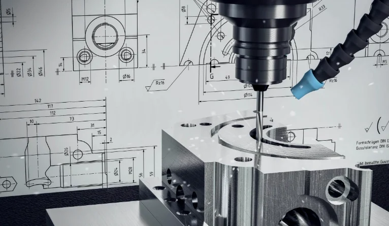
CNC router design software helps connect creative ideas with real-world making. When you build a model in CAD, each line, curve, and surface sets the base for how a router moves over the material. If that shift from digital shapes to machine actions is not smooth, even the best router might make bad parts. This piece looks at how CAD info turns into exact toolpaths. It also covers what tools in today’s software make the job more dependable and quicker.
The Role of CAD in CNC Routing?
Before cutting starts, a job begins with a CAD file. These files outline shapes—edges, surfaces, and sizes—that act as the plan for machining. In CNC routing, exactness here impacts not only the end part. It also affects tool wear, run time, and wasted material.
CAD Files as the Foundation for Toolpaths
CAD models form the basic code of your part. Every outline or line sets where a cutter goes. When you export them right, these files let the CAM part of cnc router design software figure out toolpaths that fit the design goal exactly. A tiny space or overlapping shape in the drawing can cause wild machine moves or unwanted digs.
Design Accuracy and Efficiency
Good, clear shapes cut down on fixes. If your curves are even and sizes match up, the router keeps steady speeds without extra slowdowns. This leads to neater edges and faster cutting times. For instance, in a shop I know, they once skipped cleaning a file, and it added 20 minutes per piece just from jerky paths—lesson learned.
Compatibility Between Geometry and CAM
Various machines read data in their own ways, based on post-processors and setup points. Making sure your CAD shapes line up with those details stops expensive changes later at setup. Think about a woodworker switching from a small hobby machine to a big industrial one; mismatched coords once ruined a whole batch of cabinet doors.
How CNC Router Design Software Interprets CAD Data?
When you bring a CAD file into cnc router design software, it does more than spot shapes. It reads them with math. Each layer or item type might stand for certain jobs, like digging pockets or edging profiles.
Translating Vector Geometry Into Machine Instructions
The software turns lines into G-code. It does this by turning points into tool shifts along X, Y, and Z directions. Layers usually match depth steps or tool kinds. This helps set up the order automatically. In practice, I’ve seen layers used to split a sign project into rough cuts and fine details, saving hours of hand tweaking.
Aligning Units and Coordinate Systems
A usual problem pops up when metric files go into inch setups, or the other way around. Checking that units match stops size mistakes that might wreck a full sheet of stock. One time, a friend imported a European design without checking, and everything came out twice as big—talk about a headache.
Maintaining Data Integrity During Import/Export
File damage or lost links can twist outlines. Looking over brought-in shapes before making toolpaths spots issues soon. It’s like proofreading before printing; catches the small stuff that bites later.
Core Elements of Precision in CAD-to-Toolpath Conversion
Exactness goes beyond close fits. It’s about keeping shape truth through each step from CAD to CAM to machine code. And honestly, in busy shops, skipping this leads to more coffee breaks fixing errors than actual work.
Geometric Accuracy and Model Integrity
Bad edges or repeat points often mess up toolpath making. Routers can’t handle fuzzy borders. Fixing line paths before sending out keeps smooth control over bends. For example, in metal routing, unclean geometry once caused a tool to snap mid-job, costing $50 in bits alone.
Proper Scaling and Alignment
Off-center starts between design area and machine table often mean shifted cuts. Using the same starting points keeps sizes right when cutting begins. It’s basic, but pros swear by double-checking this every time, especially with big panels over 4×8 feet.
Toolpath Generation Parameters
Feed speeds, spin rates, and overlap steps rely on material traits and shape details. Say, tough woods need slower paces than light foams, even with the same outlines. Adaptive ways like trochoidal milling keep steady tool contact. They also cut down heat, which is key for good finishes on fancy carvings.
Smart math in current cnc router design software spots extra trips on its own. Tools skip empty air spots, boosting output without losing sharpness. Picture routing 100 signs a day; trimming air time by 15% adds up to real savings on power and wear.
Software Features That Enhance Conversion Quality
Today’s routing tools offer shape flexibility, test runs, and check features built to lower shift mistakes from CAD build to machine run. These aren’t just bells and whistles; they save real time in the field.
Parametric Modeling Capabilities
Parametric setup lets you tweak sizes without redoing whole groups. For example, shift a board’s thick part, and slot depths update if links are set well. This cuts hours on changes. Auto math keeps linked shapes in step. When one bit shifts, others adjust to fit, instead of snapping ties.
It’s handy for custom furniture runs where clients change minds often. No more starting from scratch each tweak.
Integrated Simulation and Verification Tools
Test spaces work like fake routers. They show tool-material contact before real cuts. Crash checks spot extra digs or skipped spots early. Check tools even guess wear spots on tool edges from use time. This helps plan bit swaps. In one case, sim caught a deep pocket that would have hit the table, avoiding a $2000 machine fix.
Managing File Formats and Data Exchange Standards
Working across different software makers or machine types stays a top hurdle when shifting designs.
Common CAD Formats for CNC Routing Applications
DXF stays common for flat outline jobs. It keeps layer info neat across tools like AutoCAD or Fusion 360. STEP or IGES deal better with tricky 3D blocks. They hold surface maps, not just wire sketches.
Picking the right type cuts shift errors, like lost bends or split curves during bring-in or send-out in cnc router design software setups. For 2D signs, DXF is quick; for 3D molds, STEP saves headaches.
Strategies for Maintaining Data Fidelity Across Platforms
Steady layer names ease later auto jobs. Each color might mean a task—red for full cuts, blue for etch steps. Standard start points line up stacked plans over many sheets in group runs.
Eye-checking brought files before code steps guards against hidden unit swaps or turned views from mirror setups. It’s a simple habit that pros use to keep things straight, especially in teams with mixed software.
Workflow Optimization Through Software Integration?
Blending CAD build with CAM setup in one system skips repeat sends. It keeps all details linked live—a big win in varied production spots. Plus, it feels more natural, like having all tools in one toolbox instead of hunting around.
Linking CAD, CAM, and Post-processing Modules Seamlessly
All-in-one spots let design tweaks flow right into cut plans without hand work. Built-in code makers fit G-code just for each control type, from Fanuc routers to custom shop builds.
Live linking means any shape fix updates paths at once. This stops old code from running on machines with past versions—a usual scrap maker in full shops. Saves material, and tempers.
Automation and Scripting in Advanced CNC Router Design Software
Custom codes handle repeat chores, like auto fitting parts on full sheets. This maxes yield from wood boards or plastic sheets. Links to outside tracking systems let jobs follow from order to done, with reports kept in one spot for checks.
Auto steps also spot odd bits, like forgotten holes, before they spread. Saves time and stock in big lots where sameness counts. In a factory I recall, scripting cut nesting waste from 20% to under 5%—pure gold for profits.
Future Directions in CNC Router Design Software Development?
The coming wave of cnc router design software heads to smart auto help. It uses AI from past cut data, plus web team work for spread-out groups. It’s exciting, but we’ll see if it lives up to the hype in everyday shops.
AI-Assisted Design-to-Manufacturing Conversion Tools
Learning math guesses best speeds from old logs. This cuts guesswork that operators do by hand at start. AI fix tools auto mend open lines for sealed models ready for cuts, without people cleaning up. Big plus in quick test runs with mixed file types from global teams.
Guess work also tweaks spin loads during runs. It reacts to shake sensors for even finishes under uneven stock, like wood bumps or spotty composites. Imagine routing oak with hidden knots; AI smooths it out without stops.
Cloud-Based Collaboration and Real-Time Data Management
Web storage lets many users edit at once. They share linked models safely, with change logs tracking every shift from idea to final checks. Files stay remote but open anywhere through web links tied to current plant systems for trace needs in strict fields like plane parts.
This setup shines for far-off teams, say a designer in Asia tweaking for a US shop overnight. No more email chains of files; everything updates live.
FAQ
Q1: What’s the most reliable file format for importing designs into cnc router design software?
A: DXF works best for 2D profiles while STEP is preferred for complex 3D solids due to its robust handling of surface topology data structures.
Q2: How can you avoid scaling issues during conversion?
A: Always verify unit settings match between your CAD program and routing software; mismatched millimeter-to-inch conversions are among the most common causes of dimensional deviation on finished parts.
Q3: Why do some imported drawings create broken toolpaths?
A: Non-manifold edges or overlapping nodes confuse path solvers causing gaps; cleaning geometry using vector validation tools resolves these inconsistencies before generating G-code output.
Q4: What’s the advantage of parametric modeling over static drafting?
A: Parametric models let you update dependent features automatically—change one dimension like panel width and all related joints recalculate instantly preserving proportional relationships without manual redrawing effort each time revisions occur.
Q5: How does AI improve future cnc router workflows?
A: AI predicts optimal machining parameters from prior runs reducing setup experimentation while auto-correcting geometry flaws ensuring faster transitions from raw designs straight into production-ready toolpaths with minimal operator intervention needed afterward.