
What Could Go Wrong With a New CNC Setup and How to Prevent It
I Got a New CNC Machine… What Could Possibly Go Wrong?
Bringing a new CNC machine into your workshop feels like stepping into the future of precision manufacturing. The promise of automation, repeatability, and accuracy is exciting. Yet, even with modern technology, the early stages of setup can be filled with unexpected challenges. From mechanical misalignments to software quirks and environmental factors, every detail matters. Understanding these potential pitfalls helps you avoid costly downtime and maintain consistent output quality.
Common Mechanical Issues in a New CNC Setup
A CNC machine’s mechanical integrity forms the backbone of its performance. During installation, even slight deviations in alignment or balance can ripple through the system, affecting everything from tool life to surface finish.
Misalignment and Calibration Errors
Improper machine leveling is one of the most common issues during initial setup. If the base isn’t perfectly leveled, you’ll notice inaccuracies in cutting paths and uneven wear on components. Incorrect spindle alignment leads to poor surface finishes and dimensional errors that can be hard to trace back later. Regular calibration routines—especially using laser interferometers or ballbar tests—help maintain positional precision over time. It’s best practice to schedule calibration checks after transport or major maintenance work.
Vibration and Stability Concerns
Vibration is often underestimated but can quietly ruin your machining accuracy. Unbalanced loads or an unstable foundation generate resonance that transfers directly into your cutting process. The result? Shortened tool life, chatter marks on surfaces, and unpredictable tolerances. Using vibration-damping mounts or filling machine bases with polymer concrete are effective ways to increase rigidity. Even something as simple as checking floor flatness before installation can prevent long-term instability.
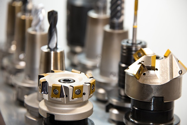
Tool Holder and Spindle Interface Problems
The interface between tool holder and spindle taper is a precision fit that demands cleanliness. Any contamination—oil residue, dust, or chips—reduces clamping force and introduces runout. Over time, this accelerates wear on both parts. Always inspect tapers for scoring or fretting corrosion under magnification if possible. Incompatible tool holders not matching the spindle’s taper angle (for example, BT40 vs CAT40) may seem similar but cause subtle misfits leading to chatter during heavy cuts.
Electrical and Control System Challenges
While mechanical issues are visible, electrical problems often hide behind intermittent faults or control errors. A solid power infrastructure and properly configured drives are essential for reliable CNC operation.
Power Supply Irregularities
Voltage fluctuations are notorious for damaging sensitive components such as servo drives or control boards. Inconsistent grounding can also introduce electrical noise that causes erratic controller behavior or false limit switch triggers. Installing surge protection devices and using dedicated circuits stabilize power delivery and protect against transient spikes from other equipment.
Servo Tuning and Drive Configuration Errors
Servo systems require precise tuning to achieve smooth motion control. Incorrect gain settings lead to overshoot, oscillation, or sluggish axis response—all symptoms that degrade machining quality. Mismatched drive parameters between motor models can cause synchronization issues in multi-axis setups. Following manufacturer-provided tuning procedures using diagnostic software ensures balanced performance across all axes.
Communication Failures Between Components
In modern CNC systems that rely on Ethernet-based protocols like EtherCAT or Profinet, communication stability is critical. Loose connectors or damaged cables interrupt data exchange between controllers and peripherals such as tool changers or probes. Network latency can disrupt real-time feedback loops required for adaptive control functions. Shielded cables with proper grounding help reduce electromagnetic interference that causes packet loss.
Software Integration and Programming Pitfalls
Even when hardware runs flawlessly, software mismatches can bring production to a halt. Post processors, toolpath generation, and controller settings must align perfectly with your specific CNC configuration.
Post Processor Compatibility Issues
Each CAM system outputs G-code differently depending on the post processor used. If it doesn’t match your machine’s controller syntax (Fanuc vs Siemens vs Haas), you’ll see unexpected moves or alarms during dry runs. Always verify post processor settings using small sample programs before full-scale machining to confirm accurate translation from CAM data to machine code.
Toolpath Optimization Oversights
Inefficient toolpaths waste time and wear out tools prematurely. Overly aggressive feed rates might look efficient on screen but cause deflection or part distortion in reality. Simulation tools within CAM software help identify potential collisions or excessive accelerations before they occur on the shop floor.
Controller Parameter Misconfiguration
Controller parameters govern acceleration ramps, jerk limits, feed rate overrides, and safety margins. If these aren’t tailored to your material type or tooling limits, you risk mechanical stress on axes or inconsistent cut quality. Reviewing default factory settings against actual application requirements prevents unnecessary strain on drives and bearings.
Environmental Factors Affecting CNC Performance
Your workshop environment plays a bigger role than many expect in maintaining precision over time.
Temperature Fluctuations in the Workshop Environment
Thermal expansion affects every component—from ball screws to spindle housings—altering dimensions subtly but enough to throw off tolerances by microns. Ambient temperature swings also change coolant viscosity and bearing preload conditions inside spindles. Maintaining stable room temperature within ±1°C improves repeatability for high-precision operations like mold making.
Contamination from Dust, Chips, or Coolant Mist
Dust accumulation may seem harmless initially but eventually clogs linear guides and optical sensors used for homing sequences. Coolant mist settling on electrical cabinets corrodes contacts slowly until intermittent faults appear months later. Installing air filtration systems near intake vents and maintaining positive air pressure inside enclosures drastically extends component lifespan.
Human Factors in CNC Setup Errors
Machines don’t make mistakes; people do—especially when documentation is incomplete or training is rushed during installation phases.
Inadequate Operator Training During Installation Phase
Operators unfamiliar with new control interfaces often misinterpret alarms or skip critical startup sequences like homing axes properly before running programs. Lack of awareness about machine-specific safety interlocks increases risk during manual jog operations or tool changes under power-on conditions. Structured training sessions provided by OEM-certified technicians build confidence across shifts.
Insufficient Documentation of Setup Procedures
Without detailed setup records—such as leveling data, fixture alignment references, spindle warm-up logs—it becomes difficult to trace root causes when problems arise later on. Consistent documentation also standardizes practices between operators so each production run starts from known baseline conditions rather than guesswork.
Preventive Strategies for Long-Term CNC Reliability
The best way to avoid recurring issues is through disciplined preventive maintenance combined with continuous monitoring technologies now common in Industry 4.0 environments.
Establishing a Preventive Maintenance Schedule
Routine checks covering lubrication points, backlash measurements, spindle vibration analysis, coolant concentration testing—all contribute to sustained accuracy over years of service life rather than months of peak performance followed by decline.
Implementing Rigorous Commissioning Protocols
Before releasing any new CNC into production mode, conduct systematic validation: verify axis travel ranges match specifications; confirm homing sensors trigger correctly; test emergency stop circuits; review safety interlocks linked with doors or guarding systems.
Continuous Process Monitoring through Data Analytics
Modern machines equipped with IoT sensors provide real-time data streams tracking load patterns, temperature gradients, even micro-vibrations at spindle bearings. Analyzing these signals allows early detection of deviations long before physical failure occurs—turning maintenance into a predictive science rather than reactive repair work.
FAQ
Q1: How often should a new CNC machine be calibrated?
A: After installation and break-in period (typically 100–200 hours), perform full calibration monthly for the first quarter; later adjust frequency based on stability trends recorded via laser measurement reports.
Q2: What’s the main cause of vibration in new setups?
A: Most early-stage vibrations stem from poor foundation design or uneven floor surfaces causing resonance at specific spindle speeds rather than internal component defects.
Q3: Can software updates affect existing post processors?
A: Yes, major CAM software updates sometimes alter output syntax requiring revalidation of post processors before use; always test small programs first after upgrading versions.
Q4: Why does coolant mist create electrical issues?
A: Fine mist particles settle onto circuit boards forming conductive paths when mixed with humidity; this leads to corrosion-induced short circuits over time if enclosures aren’t sealed properly.
Q5: What’s considered good practice for operator training?
A: Combine classroom instruction covering control logic with supervised hands-on sessions using non-production materials until operators demonstrate full procedural competence without supervision.